
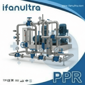
I once saw an underpowered pump struggle because someone ignored fitting pressure drops. The system never worked right. This taught me a critical lesson: every bend and valve steals pressure, and you must account for it.
You calculate the total pressure drop across multiple pipe fittings by using the “Equivalent Length” method or summing individual “K-factor” losses. These methods convert the resistance of each fitting into an amount of straight pipe or a specific pressure loss value, which you then add to the straight pipe loss to find the system’s total resistance for proper pump sizing.
Let’s break down this essential engineering step so you can avoid costly design mistakes.
What Is the “Equivalent Length” Method for Calculating Fitting Pressure Drop?
Engineers needed a simple way to compare fittings to pipe. The Equivalent Length method provides just that—a handy translation.
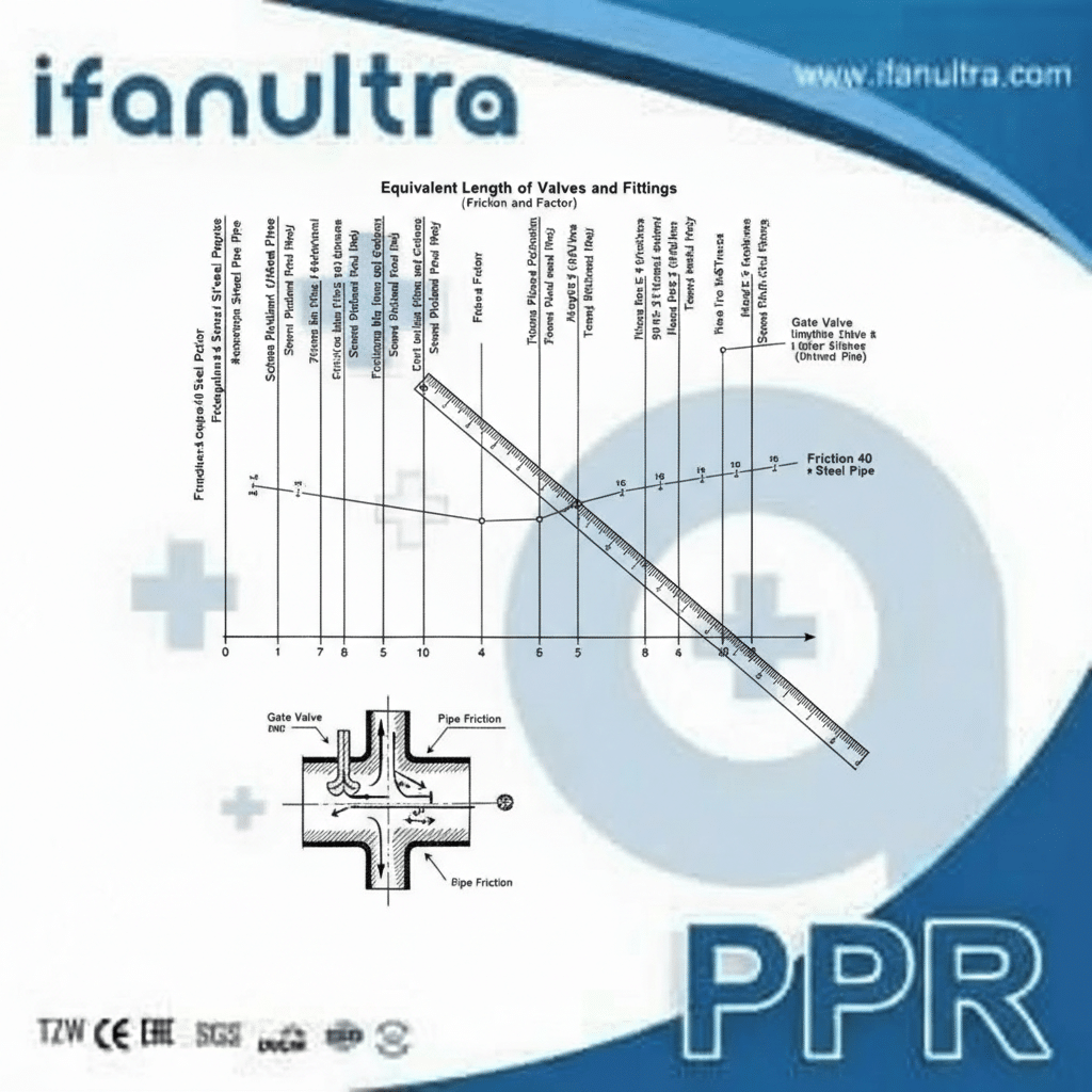
The “Equivalent Length” method calculates fitting pressure drop by assigning each fitting a length value of straight pipe that would cause the same amount of friction loss. You simply add these equivalent lengths to your total straight pipe run, then use a standard pipe friction chart to find the total pressure drop for the combined length.
The Basic Idea: Translating Fittings into Pipe
Imagine a sharp 90-degree elbow causes as much flow resistance as 5 meters of straight pipe. If you have that elbow, you pretend your pipe is 5 meters longer for your calculations. This method is popular because it is straightforward. You work with one familiar concept—pipe length—instead of complicated coefficients.
Here is how you do it step by step:
- Find the Equivalent Length: Look up a standard chart (like the one below) to see how many meters of pipe each fitting equals. This value depends on the fitting type, size, and sometimes the material.
- Tally the Total: Add up the equivalent length for every fitting in your system.
- Add to Straight Pipe: Add this total to the actual measured length of straight pipe in your system.
- Use a Friction Chart: Take this new, longer total length to a pipe friction loss chart (often called a Hazen-Williams chart). Find your flow rate and pipe diameter on the chart. It will show you the pressure loss per 100 feet or meter of pipe.
- Calculate Total Drop: Multiply the loss per unit length by your total equivalent length to get the total pressure drop.
A Practical Example
Let’s say you have a water line with 30 meters of straight pipe, four 90° elbows, and two gate valves. For a 1-inch schedule 40 pipe:
- Each 90° elbow might equal 1.7 meters.
- Each gate valve might equal 0.4 meters.
- Fitting Loss Total: (4 x 1.7m) + (2 x 0.4m) = 6.8m + 0.8m = 7.6 meters equivalent length.
- Total System Length for Calculation: 30m (real pipe) + 7.6m (fittings) = 37.6 meters.
You would then use 37.6 meters as your length on a friction chart. If the chart shows a loss of 0.3 bar per 10 meters at your flow rate, your total loss is: (37.6m / 10m) * 0.3 bar = 1.13 bar.
Advantages and Limits of This Method
This method is great for quick estimates and simpler systems. It works well for water and similar fluids. However, it is less accurate for very complex systems, gases, or highly viscous liquids. For those, the more detailed K-factor method is better.
Where Can You Find Standardized Pressure Drop Coefficients for Common Fittings?
You cannot guess these numbers. Using the wrong coefficient leads to pump failure. We rely on trusted engineering sources.
You can find standardized pressure drop coefficients (K-factors) or equivalent lengths in engineering handbooks like Crane’s “Flow of Fluids Through Valves, Fittings, and Pipe,” in standards from ASME, ANSI, or ISO, and in reputable technical manuals from pipe and fitting manufacturers. These sources provide tested values for various fitting types and sizes.

The Go-To Source: Crane’s Technical Paper
For most engineers, the primary reference is Crane’s technical paper, often called “Crane 410.” This book contains extensive tables of K-factors for virtually every type of fitting—elbows, tees, reducers, valves—under different flow conditions. It is the industry benchmark.
Manufacturer-Specific Data
Major manufacturers of valves and specialty fittings often publish their own K-factor data. This is crucial because a full-port ball valve has much less resistance than a standard-port one. A manufacturer’s catalog will list the specific “Cv” (Flow Coefficient) or K-factor for their product. Always check here for precise data on the exact components you plan to use.
Standardized Reference Tables
For common generic fittings, summary tables are widely available online and in textbooks. Here is a simplified example of K-factors for standard threaded fittings in turbulent flow:
| Fitting Type | Typical Resistance Coefficient (K-factor) |
|---|---|
| Standard 90° Elbow | 0.9 – 1.0 |
| Standard 45° Elbow | 0.4 – 0.5 |
| Tee (Straight Flow) | 0.5 – 0.6 |
| Tee (Branch Flow) | 1.5 – 1.8 |
| Gate Valve (Fully Open) | 0.2 – 0.3 |
| Globe Valve (Fully Open) | 6.0 – 10.0 |
| Check Valve (Swing Type) | 2.0 – 3.0 |
Important Note: These are approximate values. The exact number depends on pipe size, roughness, and Reynolds number (which indicates turbulent or laminar flow). For a real design, you must consult detailed charts that account for these variables.
A Critical Warning About “Standard” Assumptions
A common mistake is assuming all fittings of the same name have the same resistance. A long-radius elbow has a much lower K-factor than a short-radius or mitered elbow. Using the wrong value can cause a 50-100% error in your calculation. Always note the specific fitting geometry your data references.
How Do You Sum the Pressure Loss from All Fittings in a Piping System?
You have the coefficients; now you need to do the math. The process is methodical but simple.
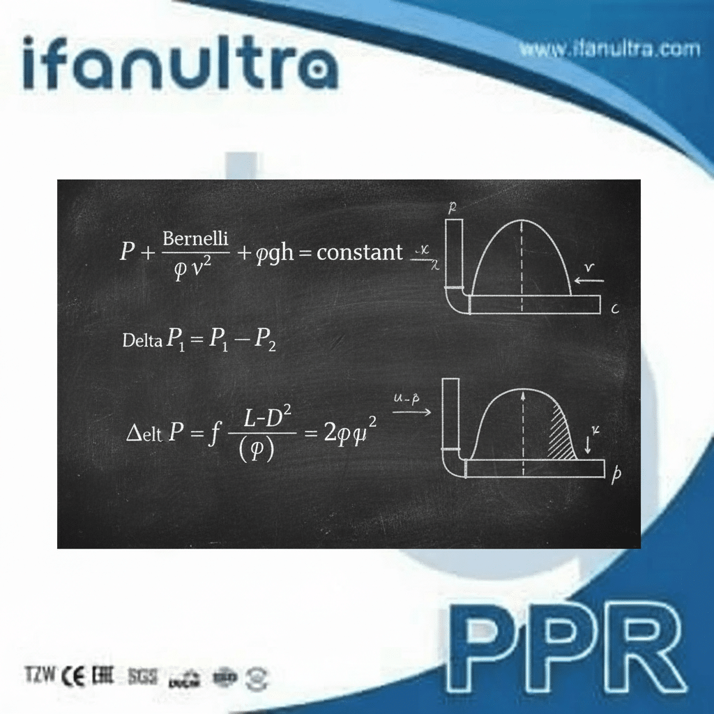
You sum the pressure loss from all fittings using this core formula for each fitting: ΔP = K * (ρ * v² / 2). First, find the K-factor for each fitting, calculate the fluid’s density (ρ) and velocity (v), then compute and add the loss for each one. Finally, add the total fitting loss to the straight pipe pressure loss.
Step-by-Step Calculation Using K-Factors
Let’s walk through the detailed process. This method is more universal than the equivalent length approach.
- List All Fittings: Make a complete list of every valve, elbow, tee, and reducer in your pipeline.
- Get the K-factor: Find the correct resistance coefficient (K) for each fitting from your reference tables.
- Calculate Fluid Velocity (v): You need to know how fast the fluid is moving.
- Formula: v = Q / A
- Q = Flow Rate (m³/s or GPM)
- A = Internal Cross-Sectional Area of the Pipe (m² or ft²)
- Calculate the Velocity Head (ρv²/2):
- This is a key energy term.
- ρ (rho) = fluid density (kg/m³ or lb/ft³).
- Calculate v² (velocity squared), multiply by density, and divide by 2.
- Calculate Loss per Fitting: For each fitting, multiply its K-factor by the Velocity Head.
- Formula for one fitting: ΔP_fitting = K * (ρ * v² / 2)
- The result will be in units of pressure (Pascals, psi, etc.).
- Sum All Fitting Losses: Add up the ΔP from every single fitting. This is ΔP_fittings_total.
- Calculate Straight Pipe Loss: Use the Darcy-Weisbach or Hazen-Williams equation to find the pressure loss for the actual length of straight pipe. This is ΔP_pipe.
- Find Total System Pressure Drop: Add them together.
- Total ΔP_system = ΔP_pipe + ΔP_fittings_total
A Simple Example in a Table
Assume water (ρ = 1000 kg/m³) flows at 0.01 m³/s in a 0.1m diameter pipe (Area A ≈ 0.00785 m²). Velocity (v) = Q/A = 1.27 m/s. Velocity Head = (1000 * 1.27²) / 2 = 806 Pa.
| Fitting | Quantity | K-factor (each) | Total K | Pressure Loss (ΔP) |
|---|---|---|---|---|
| Codo de 90 | 4 | 0.9 | 3.6 | 3.6 * 806 Pa = 2902 Pa |
| Tee (Straight) | 2 | 0.5 | 1.0 | 1.0 * 806 Pa = 806 Pa |
| Gate Valve | 1 | 0.2 | 0.2 | 0.2 * 806 Pa = 161 Pa |
| Total Fitting Loss | 4.8 | Σ = 3869 Pa |
If the straight pipe loss (ΔP_pipe) is calculated as 5000 Pa, then the Total System ΔP = 5000 + 3869 = 8869 Pa.
This table makes the summation clear and organized, preventing errors.
Why Is Accurate Pressure Drop Calculation Critical for Proper Pump Selection?
This is where theory meets reality. A wrong calculation here costs thousands in wasted energy or a failed system.
Accurate pressure drop calculation is critical because it directly determines the required pump head. An underestimate leads to a pump that cannot deliver enough flow, causing system failure. An overestimate selects an oversized, inefficient pump that wastes energy, increases costs, and may cause control problems like cavitation and excess wear.
Consequences of Underestimating Pressure Drop
If you ignore fittings or use wrong coefficients, your calculated system resistance will be too low.
- The Problem: You buy a pump designed for, say, 50 feet of head. The actual system, with all fitting losses, needs 70 feet.
- The Result: The pump cannot overcome the extra resistance. Flow rate drops to zero or a trickle. The system does not work. The pump motor may also overheat trying to push against the high resistance, leading to burnout.
- The Fix: You must replace the pump, repipe the system to reduce resistance, or add a second booster pump—all very expensive solutions.
Consequences of Overestimating Pressure Drop
Being overly conservative is also a major mistake.
- The Problem: You calculate a need for 100 feet of head, but the real system only needs 70 feet.
- The Result: You install a larger, more powerful pump. It will deliver the required flow, but it will do so by operating far to the right on its performance curve.
- High Energy Waste: The pump consumes much more electricity than necessary.
- Control Issues: To reduce flow, you must throttle a valve, which wastes even more energy as heat and noise.
- Cavitation Risk: Higher pressure and velocity can cause cavitation (the formation and collapse of bubbles), which destroys impellers.
- Excess Wear: The pump and seals experience higher stresses, shortening their life.
The Financial Impact: Energy Costs
The energy waste from an oversized pump is huge. A pump’s power consumption is roughly proportional to the flow rate * the head it produces. An extra 10-20% of unnecessary head can increase energy costs by 15-30% over the pump’s lifetime, which could be tens of thousands of dollars.
The Right Way: Matching the Pump to the System Curve
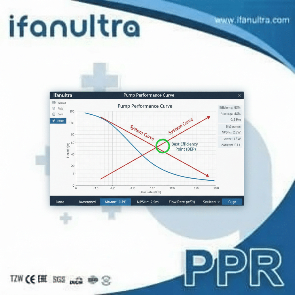
An accurate pressure drop calculation lets you plot the true “System Curve.” The pump’s performance curve should intersect this system curve exactly at your desired flow rate. This ensures efficient, reliable, and long-lasting operation. It is the single most important outcome of your hydraulic calculations.
| Calculation Error | Result on Pump Selection | Operational Consequence |
|---|---|---|
| Significant Underestimate | Pump too small | System Failure: No flow, motor overload, shutdown. |
| Slight Underestimate | Pump slightly small | Reduced Performance: Lower than needed flow rate. |
| Accurate Calculation | Pump correctly sized | Optimal Operation: Correct flow, high efficiency, long life. |
| Slight Overestimate | Pump slightly large | Inefficiency: Throttling required, higher energy bills. |
| Significant Overestimate | Pump far too large | Major Waste & Damage: Very high energy costs, cavitation, control problems. |
Conclusión
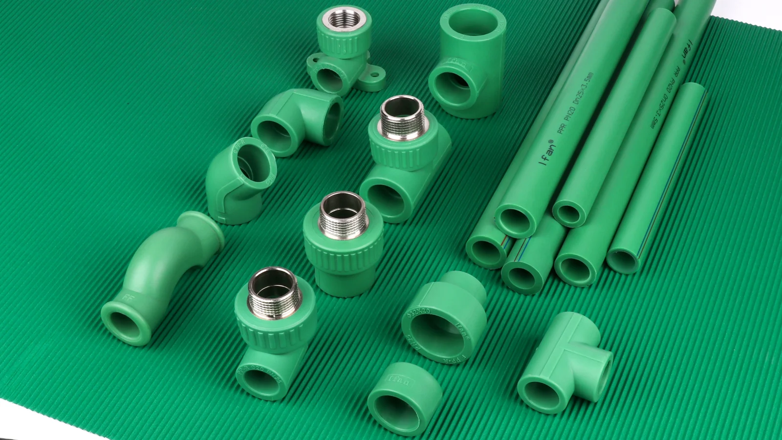
Accurate pressure drop calculation is essential for efficient, functional piping systems. For predictable, low-resistance performance, design your system with high-quality fittings from IFAN, where consistent dimensions ensure your calculations match reality.



 English
 Español
 Français
 Português do Brasil