
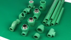
For a completely full, straight PP-R pipe, calculate water volume in litres as π × internal diameter² × installed length ÷ 4,000, with bore in millimetres and length in metres. Obtain the bore from the actual product data, or subtract twice the wall from the outside diameter. Calculate each different section separately, then add only the sections and equipment inside the intended fill boundary.
A project schedule that says “40 metres of 32 mm PP-R” is a start. It still lacks the wall or actual bore needed for the calculation. A whole-circuit total also needs a boundary: the return, branches and connected equipment may belong in the inventory, or they may be isolated outside this particular fill. The method below produces a transparent pipe subtotal and makes the unfinished parts visible.

Draw the fill boundary before measuring pipe
Start with the drawing or installed section list and identify the part of the system the number is meant to describe. “Water in the building” and “water in the isolated floor circuit” are different totals even when both calculations use the same pipe schedule. Give the inventory a name and mark its endpoints. A dated drawing reference makes later changes easier to reconcile.
List each included run once. Where a common feed divides into two branches, the feed is one row and each branch is another. Adding the complete source-to-outlet path for every outlet would count the shared feed repeatedly. The same issue occurs when someone adds a complete circuit length to a separate return length that was already included in that circuit figure.
Use installed geometric pipe lengths, with the measurement convention recorded. Purchased lengths include offcuts and unused stock; those pieces do not hold water in the completed circuit. An approximate centreline drawing take-off can be useful for planning, but label it as such. If the required accuracy calls for separate component volumes, establish pipe lengths between the chosen component boundaries and add component capacities consistently, without counting the same space twice.
Separate pipework from heaters, coils, vessels, valves and other fittings. A pipe-only calculation can be complete on its own terms while the whole-system inventory remains unfinished. Record each additional capacity from the actual equipment documentation or an appropriate project measurement. If that information is missing, keep the line open. The geometry calculation is not a reason to assume every connected item contains a negligible volume.

Read the bore from the actual pipe series
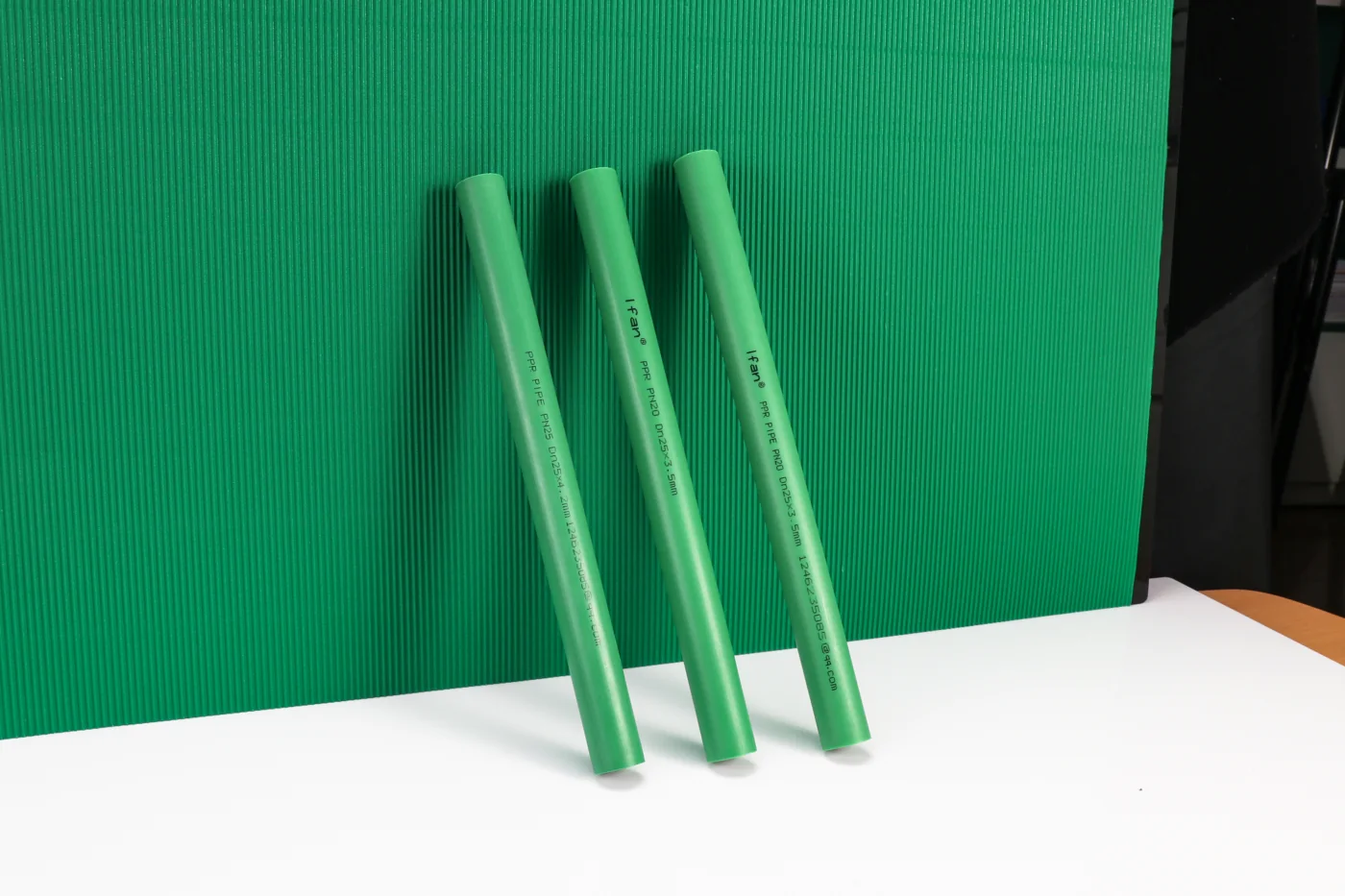
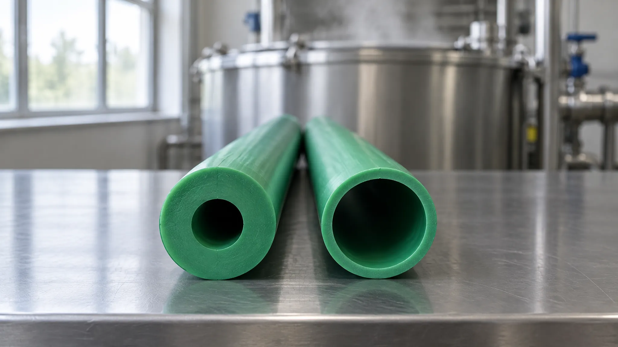
The circular space holding the water is inside the wall. For a pipe represented by an outside diameter D and uniform wall thickness t, the internal diameter d is D − 2t. Keep all three dimensions in the same unit. A size name, an inch equivalent or a PN marking alone does not supply every input for this calculation.
Use the manufacturer, product series and dimension pair attached to the installed pipe. Check that the document describes the same construction rather than another plain or composite line. The PP-R dimensions and tolerance reference provides the broader dimensional context; a retained-water estimate still needs the particular geometry being used in this inventory.
Here is a documented example rather than a universal PP-R size table. Aquatherm’s August 2023 green catalogue lists a 32 mm outside diameter, 5.4 mm wall and 21.2 mm internal diameter for one SDR 6 entry. A 25 mm entry has a 4.2 mm wall and 16.6 mm bore. These historical third-party dimensions are used only to demonstrate the arithmetic below. They are not a current IFANULTRA specification or confirmation that a particular model is available. See the manufacturer catalogue, printed pages 80–81.
If the schedule gives only an outside size, mark the bore as missing and resolve the product identity or dimension data before calculating that row. Copying the bore from the nearest-looking pipe would create a definite answer from an uncertain input. For a dimensional planning estimate, declared nominal geometry is appropriate when labelled; an inventory requiring tighter accuracy needs the agreed actual dimensional or measured-volume basis.
Calculate one segment in litres
A full straight circular bore is a cylinder. Its cross-sectional area is πd²/4, and multiplying by length gives volume. When d is in millimetres and L is in metres, converting the area and resulting cubic metres to litres leaves the following compact expression:
d = internal diameter in mm; L = installed length in m
Assume, for teaching purposes, a 40 m straight-pipe total with the catalogue example’s 21.2 mm bore. The length is an illustrative input, not a measured project. Substitution gives π × 21.2² × 40 ÷ 4,000 = 14.1196 L, reported here as approximately 14.12 L of pipe capacity. An ordinary spreadsheet expression is =PI()*21.2^2*40/4000. Put the inputs in separate labelled cells when building a reusable sheet.
The diameter term is squared. Entering the 32 mm outside diameter instead would give about 32.17 L for the same assumed length. That larger answer includes the space occupied by the wall: it is not the water capacity. This is why identifying the bore is more consequential than carrying extra decimal places through the final total.
The same dimensional derivation gives litres per metre by setting length to one metre: πd²/4,000. A printed L/m value can also be multiplied by length when it belongs to the exact product. Check how it is rounded. For the 21.2 mm example, calculating from the displayed bore gives about 0.352989 L/m; the catalogue prints 0.353 L/m. Either route is transparent if the chosen basis is stated, but a rounded catalogue factor should not be presented as an exact physical measurement.
Keep full precision in the calculation and round the displayed subtotal at the end. A hundredth of a litre in a worked example shows how the arithmetic was performed; it does not establish that a drawing take-off, nominal bore or complete installed system is known to that precision.
Add the sections without hiding missing volumes
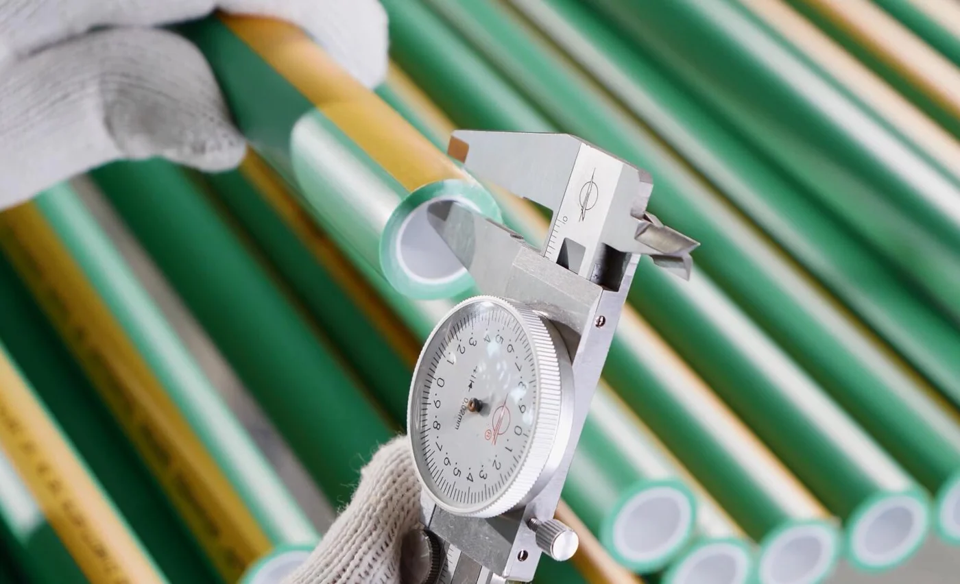
Now add a second teaching section: 20 m of pipe with the historical example’s 16.6 mm bore. Its capacity is π × 16.6² × 20 ÷ 4,000 = approximately 4.33 L. Adding the unrounded results produces 18.4481 L, displayed as an 18.45 L pipe-only subtotal. The two lengths are hypothetical; the dimension examples are documented. No actual customer fill or commissioned installation is represented.
| Row and scope | OD × wall (mm) | Bore (mm) | Length (m) | Capacity (litres) |
|---|---|---|---|---|
| A: included main | 32 × 5.4 | 21.2 | 40, assumed | 14.12 |
| B: included branch | 25 × 4.2 | 16.6 | 20, assumed | 4.33 |
| A + B pipe subtotal | Two geometry groups | As above | 60 combined | 18.45 |
| C: optional return | 25 × 4.2 | 16.6 | 12, assumed | 2.60 if included |
| Connected equipment and fittings | Actual component references needed | Not inferred | Separate capacity basis | Unresolved |
Change the boundary and the answer changes. If the assumed 12 m return is included in this filled circuit and has not already been counted, add its unrounded 2.5971 L. The pipe subtotal becomes approximately 21.05 L. If that return is outside this inventory’s defined boundary, retain the 18.45 L subtotal and mark the return excluded. This is an accounting decision based on the documented system state; it is not an instruction to operate an isolation valve.
The equipment row remains unresolved in both cases. Writing 21.05 L beside “whole system” would overstate what the sheet proves. Label it “included straight-pipe subtotal; equipment and fittings pending” until their capacities and inclusion are established. Where an item has already been included through another documented measurement, identify that fact rather than adding it twice.
| Record | What to enter | Rule when missing |
|---|---|---|
| Scope and row identity | Circuit, endpoints, included/excluded state and drawing reference | Resolve the boundary before summing |
| Pipe geometry | Manufacturer, series, document revision, OD/wall or actual bore | Hold that row until bore is established |
| Installed length | Metres and measurement convention | Complete the take-off; exclude unused stock |
| Other components | Capacity source, quantity and inclusion state | Keep the whole-system total incomplete |
| Result basis | Formula or product L/m factor, rounding and known exclusions | Do not issue an unlabelled total |
Inventory procedure
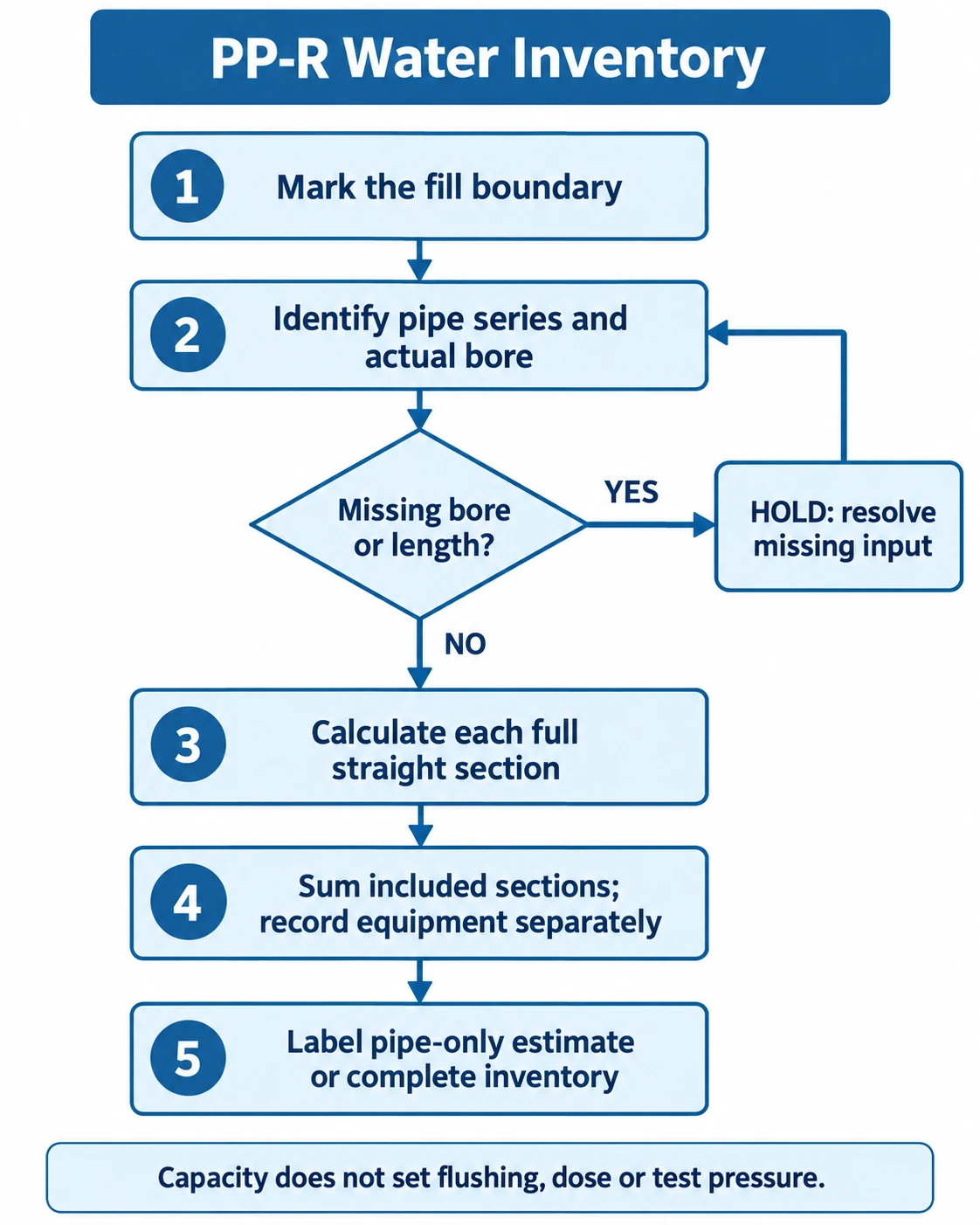
- Mark the fill boundary and identify the included sections.
- Identify each pipe series and actual bore. If bore or length is missing, hold the calculation and resolve that input.
- Calculate each full straight section in litres.
- Sum the included sections and record equipment and fittings separately.
- Label the result as a pipe-only estimate or a completed inventory, according to the inputs actually resolved.
Keep capacity separate from commissioning water
The result describes the geometric capacity of the stated full pipe sections. It does not tell the team how much water an operational fill, flushing operation or pressure test will consume. A metered quantity can include water discharged elsewhere or retained outside the defined section list; a nominal geometry estimate and a site reading therefore need the same boundary before they can be compared.
Likewise, this arithmetic does not calculate flow rate. Litres of retained water and litres per minute are different quantities. Nor does the inventory select a pipe diameter, establish acceptable pressure loss or prove that an existing line meets fixture demand. Keep those design checks with the project’s applicable method rather than treating a larger capacity as a better design.
For commissioning, pass the inventory to the person responsible for the actual procedure, together with the product identity, boundary and outstanding items. That procedure must establish its own operating conditions and acceptance criteria. No universal flushing multiple, disinfectant concentration, exposure time or hydrostatic test pressure follows from this volume calculation. The useful handoff is a clear input record, not an improvised treatment instruction.
If the exercise leads to a pipe or fitting enquiry, the same discipline helps procurement. Include the project country, actual manufacturer and series, OD and wall, required duty, drawing and component references. Ask whether a matching product can be supplied before relying on a quotation or assuming interchangeability. The IFANULTRA PP-R product categories are a starting point for that discussion; the example dimensions above do not confirm an IFANULTRA model, stock or a complete system’s capacity.
Have the circuit geometry identified? Review the PP-R categories, then submit the required specification for an availability check.
Conclusión
A usable water-volume record has a defined boundary, an identified bore for every pipe group and an installed length counted once. Calculate the included sections, keep unresolved component capacities visible and label the resulting subtotal accurately. That gives the next project decision a reproducible input without turning a capacity estimate into a commissioning approval.
Frequently asked questions
Does a vertical pipe hold more water than a horizontal one?
A completely full straight pipe with the same bore and length has the same geometric capacity in either orientation. Orientation can affect drainage and trapped-air conditions, which this full-pipe calculation does not model.
Can I calculate pipe capacity from kilograms per metre?
Pipe mass describes the solid material, not the hollow water space. Use the actual bore and length, or the exact product’s documented water-content factor.
Can I use this formula for a partly filled pipe?
No. The formula here assumes the whole circular bore is full. A partly filled section needs its actual liquid geometry and level; its full capacity does not describe the water currently present.



 English
 Español
 Français
 Português do Brasil