
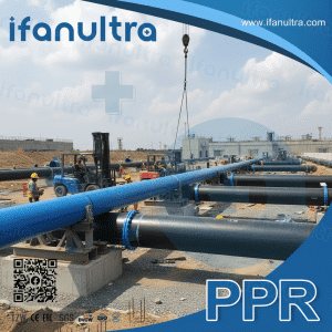
I once visited a job site where poorly supported HDPE pipes had sagged so badly that the joints were visibly pulling apart. That costly mistake taught me that proper support is not optional—it is essential.
Properly supporting and clamping large-diameter HDPE pipes requires following specific spacing guidelines based on pipe diameter, using clamps that allow axial movement for thermal expansion, selecting the correct clamp types with protective liners to prevent point stress, and understanding how improper support leads to sagging, stress concentration, and eventual joint failure. Getting these elements right ensures your HDPE system performs reliably for decades.
Let’s walk through the key principles of HDPE pipe support so you can avoid the common pitfalls we see in the field.
What Is the Maximum Recommended Support Spacing for Different HDPE Diameters?
I often see installers guess at support spacing, treating all pipes the same. That approach leads to sagging pipes and stressed joints.
The maximum support spacing for HDPE pipes depends primarily on the pipe diameter, wall thickness (DR rating), and operating temperature. For horizontal runs, supports typically need to be placed every 2 to 3 meters for smaller diameters, with spacing increasing for larger pipes. Industry standards recommend supports at intervals of no more than 1.5 meters for general storage and installation, with closer spacing for higher temperatures.

Why Spacing Matters
HDPE is a flexible material. Unlike rigid metal pipes, HDPE will sag under its own weight if supports are too far apart. This sagging creates low points where water can collect, puts stress on joints, and makes the system look unprofessional.
The correct spacing depends on several factors:
1. Pipe Diameter and Wall Thickness
Larger diameter pipes are heavier and need more frequent support. Thicker walls (lower DR numbers) make the pipe stiffer, allowing slightly wider spacing. Thinner walls (higher DR numbers) are more flexible and need closer supports.
2. Operating Temperature
HDPE softens as temperature increases. A pipe carrying hot water needs closer supports than the same pipe carrying cold water. At elevated temperatures, the material’s stiffness decreases significantly .
3. Fluid Density
Pipes carrying water need to support that water weight. Heavier fluids mean additional load on the supports.
General Spacing Guidelines
Based on industry practice and installation standards, here are recommended support spacings for horizontal HDPE pipes:
| Pipe Diameter (mm) | Cold Water (20°C) | Hot Water (40°C) | Hot Water (60°C) |
|---|---|---|---|
| 50-75 mm | 1.2 – 1.5 m | 1.0 – 1.2 m | 0.8 – 1.0 m |
| 90-160 mm | 1.5 – 2.0 m | 1.2 – 1.5 m | 1.0 – 1.2 m |
| 200-315 mm | 2.0 – 2.5 m | 1.5 – 2.0 m | 1.2 – 1.5 m |
| >315 mm | 2.5 – 3.0 m | 2.0 – 2.5 m | 1.5 – 2.0 m |
These are general guidelines. Always consult the pipe manufacturer’s recommendations for your specific product and application.
For vertical runs, supports can typically be spaced further apart, but you must account for the weight of the water column and provide adequate support at the base.
Why Must Clamps Allow for Axial Movement Due to Thermal Expansion?
A client once called us because their above-ground HDPE line had buckled and pulled away from its anchors. The problem was simple: they clamped it like steel pipe and gave it no room to move.
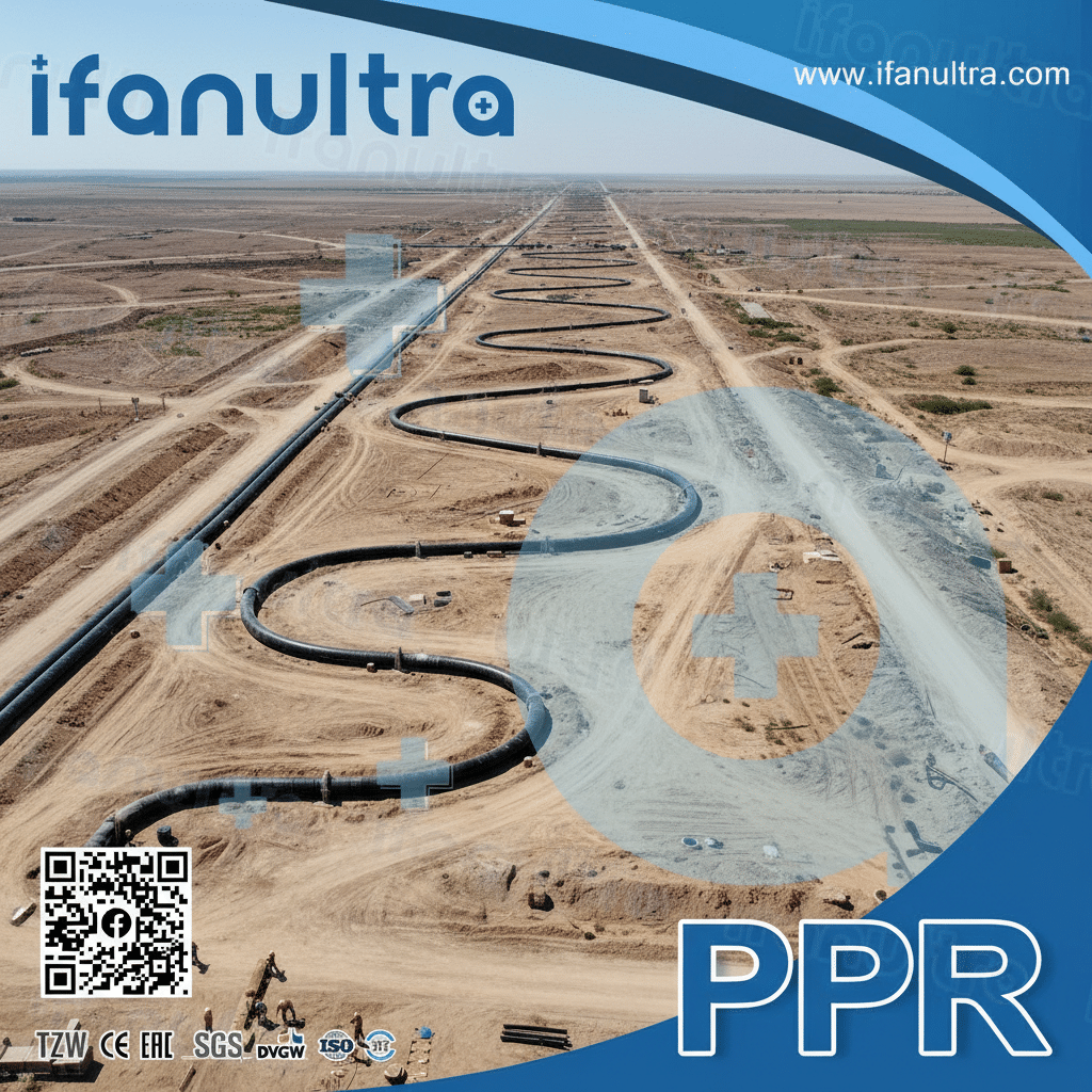
HDPE expands and contracts with temperature changes much more than metal pipes—approximately 10 times more than steel. Its coefficient of thermal expansion is about 9 x 10⁻⁵ in/in/°F . If you clamp HDPE rigidly at both ends, thermal expansion creates enormous compressive stress, causing the pipe to buckle, pull out of fittings, or fail at the joints. Clamps must allow controlled axial movement while maintaining lateral support.
Understanding HDPE’s Thermal Behavior
HDPE’s high thermal expansion coefficient means that a 100-meter pipe experiencing a 30°C temperature change will expand or contract by approximately 270 millimeters. That is over 10 inches of movement.
If you restrain both ends of that pipe completely, you are essentially trying to compress a plastic pipe like a spring. The pipe cannot compress, so it buckles sideways or pulls apart at joints. This is not a theoretical problem—I have seen it happen on multiple projects.
The Solution: Allow Movement
The proper approach uses a combination of fixed points and sliding guides:
Fixed Points (Anchors): These are placed at specific locations—typically at changes in direction, at heavy fittings, or at intervals along long straight runs. Fixed points absorb the thrust forces and divide the pipeline into manageable sections . They hold the pipe firmly in place at those locations.
Sliding Guides (Adjustable Clamps): These allow the pipe to move axially while preventing lateral movement. The pipe should be able to slide through the clamp as it expands and contracts. This requires:
- Clamps that do not tighten completely around the pipe
- Smooth, low-friction surfaces inside the clamp
- Proper spacing to prevent the pipe from sagging between supports
Designing for Movement
For above-ground pipelines, you need to calculate the expected expansion and design the support system accordingly. Key considerations include:
- Guide Spacing: Place sliding guides at regular intervals to control the pipe’s path while allowing movement.
- Expansion Loops or Offsets: For long runs, incorporate changes in direction that can absorb movement, similar to expansion joints in other materials.
- Proper Clamp Design: Use clamps specifically designed for HDPE that allow axial movement, such as adjustable sliding clamps with low-friction liners .
The table below shows typical movement for common pipe lengths:
| Pipe Length (m) | Temperature Change 20°C | Temperature Change 40°C |
|---|---|---|
| 50 m | 90 mm (3.5 in) | 180 mm (7.1 in) |
| 100 m | 180 mm (7.1 in) | 360 mm (14.2 in) |
| 200 m | 360 mm (14.2 in) | 720 mm (28.3 in) |
As you can see, the movement is significant. Ignoring it guarantees failure.
What Are the Correct Types of Clamps and Liners to Avoid Point Stress on HDPE?
A contractor once showed me a grooved and damaged HDPE pipe where a standard metal U-bolt had been tightened directly against the pipe. The damage was permanent, and the pipe had to be replaced.
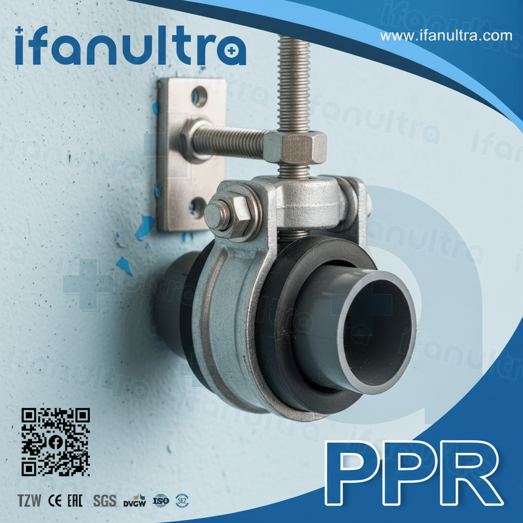
The correct clamps for HDPE pipes feature smooth, broad contact surfaces and protective liners made from materials like HDPE, polypropylene, or elastomers. These liners distribute the load evenly and prevent the pipe from contacting sharp metal edges. Clamps should be sized to fit the pipe properly without overtightening, and designs like split-ring clamps, saddle clamps, or adjustable guides with low-friction inserts are preferred .
Why Standard Clamps Fail on HDPE
Metal clamps designed for steel pipe create several problems when used on HDPE:
Point Loading: A standard U-bolt concentrates force at a few small points. HDPE is soft enough that these points will deform over time, creating stress concentrations.
Sharp Edges: Metal clamps often have burrs or sharp edges that can cut into the HDPE surface. Even small scratches can become stress risers that lead to cracking.
No Movement Allowed: Metal clamps that tighten firmly around the pipe prevent the axial movement that HDPE needs, turning the clamp into an unintended fixed point.
Galvanic Concerns: While HDPE does not corrode, metal clamps can rust and expand, further damaging the pipe.
Proper Clamp Types for HDPE
1. Sliding Guides with Low-Friction Inserts
These are specifically designed for HDPE. They feature a steel outer hoop for strength and an inner liner made of HDPE or another low-friction material. The liner allows the pipe to slide easily during thermal expansion. Some designs maintain a small gap—typically 3 mm—around the pipe to ensure unrestricted axial movement while providing lateral support .
2. Split-Ring Clamps with Elastomeric Liners
These provide 360-degree support around the pipe. The elastomeric liner cushions the pipe, distributes the load evenly, and absorbs vibrations. They are excellent for fixed points or where vibration dampening is needed .
3. Saddle Clamps
For branch connections or situations where you need to support the pipe without encircling it completely, saddle clamps distribute the load across a wider area. The curved saddle matches the pipe’s outer diameter .
4. Vibration Dampening Clamps
In areas near pumps or equipment, clamps with rubber or elastomeric liners absorb mechanical vibrations, reducing noise and protecting the pipe from fatigue damage .
Clamp Selection Guide
| Aplicación | Recommended Clamp Type | Liner Material | Key Feature |
|---|---|---|---|
| Long straight runs (above ground) | Adjustable sliding guides | HDPE or PTFE | Allows axial movement |
| Fixed points / Anchors | Heavy-duty split-ring | EPDM or rubber | Prevents all movement at that point |
| Near pumps or equipment | Vibration dampening | Elastomeric | Absorbs vibration and noise |
| Branch connections | Saddle clamp | EPDM | Supports branch without cutting main line |
| Vertical runs | Split-ring with liner | HDPE or rubber | Prevents slipping under load |
Critical Installation Tip: Never overtighten clamps. The goal is to support the pipe, not crush it. For sliding guides, the pipe should be able to move freely. For fixed points, use clamps designed to absorb thrust forces without damaging the pipe .
How Does Improper Support Lead to Sagging, Stress, and Eventual Joint Failure?
I have inspected dozens of failed HDPE installations, and almost every one traced back to poor support. The failure chain is predictable—and preventable.
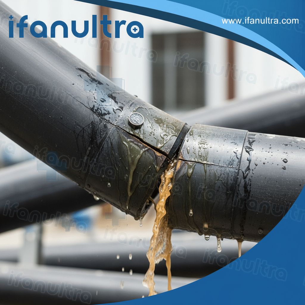
Improper support creates a cascade of problems: sagging between supports concentrates bending stress, especially at joints; restrained thermal expansion builds up compressive forces that seek release through buckling or joint separation; point loading from incorrect clamps creates localized deformation and stress risers; and over time, these combined stresses exceed the material’s limits, leading to cracking, leaks, or complete joint failure. The pipe does not fail all at once—it fails slowly, then suddenly.
The Failure Chain Explained
Stage 1: Sagging
When supports are too far apart, the pipe begins to sag under its own weight and the weight of the fluid inside. This sagging creates:
- Low points where water collects (even in drainage systems)
- Visual deflection that looks unprofessional
- Bending stress along the pipe wall
Stage 2: Stress Concentration at Joints
HDPE joints—whether butt-fused, electrofused, or mechanical—are typically the strongest points in the system. However, they are also the least flexible. When the pipe sags, the joint becomes a fulcrum point where bending stress concentrates. The pipe on either side flexes, but the joint tries to remain rigid. This creates a stress riser at the fusion boundary.
Stage 3: Thermal Expansion Restraint
If the pipe is clamped too tightly or at too many points, it cannot expand and contract freely. As temperature changes, compressive or tensile stress builds up along the entire pipeline. This stress adds to the bending stress from sagging.
Stage 4: Point Loading
Using the wrong clamps—like bare metal U-bolts—creates additional localized stress. The pipe wall deforms slightly at these points, creating ovalization. This ovalization concentrates stress at specific spots around the circumference.
Stage 5: Material Fatigue and Failure
HDPE is a viscoelastic material. It can handle stress, but it cannot handle sustained, concentrated stress indefinitely. Over time, the combined effects of:
- Cyclical stress from daily temperature changes
- Constant bending stress from sagging
- Localized point loading
- Pressure surges from normal operation
…cause micro-cracks to form. These cracks grow slowly, often invisibly, until they reach a critical size. Then, suddenly, the pipe cracks through, a joint separates, or a fitting fails.
Consequences of Failure
| Problema | Primary Cause | Resulting Damage |
|---|---|---|
| Sagging | Support spacing too wide | Water pooling, visual deflection, joint stress |
| Buckling | Thermal expansion without allowance | Pipe pushes up or sideways, pulling out of fittings |
| Cracking at fusion joints | Bending stress + restrained expansion | Hidden leaks, eventual complete separation |
| Ovalization | Over-tightened clamps | Reduced flow capacity, stress risers |
| Abrasion wear | Movement against unlined clamps | Wall thinning, eventual pinhole leaks |
Real-World Example
We worked on a project where a 315mm HDPE line was installed above ground with supports at 5-meter intervals—far too wide. Within six months, the pipe had sagged visibly between supports. Within one year, a butt-fusion joint at the midpoint of a span cracked and began leaking. The repair required cutting out a 6-meter section and re-fusing new pipe, plus adding intermediate supports. The total cost was many times higher than doing it right the first time.
Prevention Checklist
To avoid these failures:
- Calculate required spacing based on diameter, temperature, and application—do not guess
- Use proper clamps with liners and the correct fit
- Design for thermal movement with fixed points and sliding guides
- Inspect during installation to catch sagging or misalignment early
- Consider temperature extremes—pipes in direct sunlight get much hotter than air temperature
Conclusión
Properly supporting large-diameter HDPE pipes requires correct spacing, clamps that allow thermal movement, protective liners to prevent point stress, and understanding the consequences of getting it wrong. For reliable, long-lasting installations, choose IFAN’s complete range of HDPE pipes and support systems, engineered to work together for optimal performance.


 English
 Español
 Français
 Português do Brasil