
A PP-R manufacturer’s maximum recommended velocity is a screening condition, not a design target. Select the actual product and service, calculate speed from flow and internal bore, then check pressure loss, surge and noise before accepting a smaller pipe. A candidate below a published maximum can still leave too little pressure at the outlet. A higher conditional allowance can also be unsuitable for the valves and operating duty in the proposed system.
This guide addresses a water-line sizing decision: whether a smaller candidate remains acceptable when its velocity rises. It does not set a universal maximum for all polypropylene products, supply a pump design, or approve a hot-water recirculation application.
Key Takeaways
- Keep every velocity figure attached to its product, size range, service and conditions.
- Calculate speed with internal bore, not nominal diameter or outside diameter.
- A velocity pass does not prove adequate remaining pressure.
- Do not adopt a high-velocity exception when its surge conditions are absent or unknown.
- Acoustic criteria and a pipe manufacturer’s recommendation answer different design questions.
- Record the accepted flow and operating states alongside the chosen pipe and fitting system.
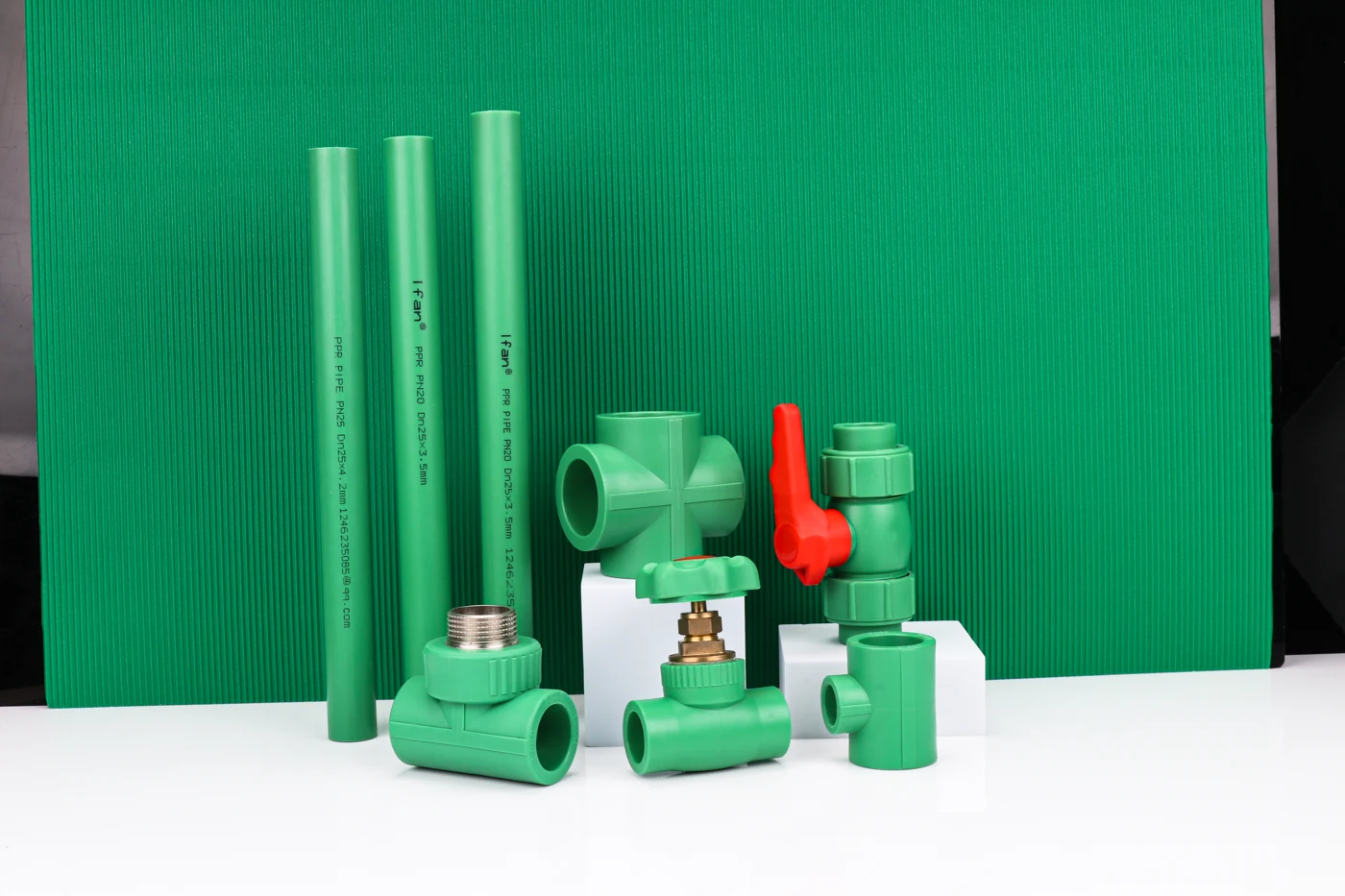
Related video: IFAN PPR Pipe Fittings — IFANPPR

Own PP-R product background for identifying pipes and fittings. This video does not assign a velocity limit or approve the teaching candidates. Open on YouTube
Name the condition before naming a velocity
A number such as 2 m/s can describe an acoustic sizing criterion. Another number can be a manufacturer’s recommended maximum for a particular pipe range. A third can describe a specially reviewed operating case. Removing those labels produces a false conflict between numbers that never answered the same question.
The Aquatherm North America June 2025 design guide, section 3.07 lists maximum recommended design velocities by size. Its 20–160 mm range is 8 ft/s, shown as 2.44 m/s; the 200–250 mm range is 10 ft/s, shown as 3.05 m/s. Those are that source’s recommendations for its systems. They are not an IFAN ULTRA rating or a universal plumbing-code limit.
The KELEN PP-R handbook presents a different context: its dimensioning discussion advises no more than 2 m/s in collective feeds, risers and multi-storey pipes with regard to flow noise, while describing up to 4 m/s for individual feeds. This is useful evidence that location and design purpose matter. It does not prove that all other brands accept the same figures.
| Retrieved source | Criterio | Alcance | Verdict |
|---|---|---|---|
| Aquatherm June 2025 | 8 ft/s (2.44 m/s) | 20–160 mm source product range | Source-specific recommendation |
| Aquatherm June 2025 | 10 ft/s (3.05 m/s) | 200–250 mm source product range | Do not apply smaller-size row blindly |
| KELEN handbook | 2 m/s | Collective feeds/risers; flow-noise discussion | Acoustic context remains attached |
| KELEN handbook | Up to 4 m/s | Individual feeds in that guidance | Not a general riser allowance |
For a real candidate, identify the exact applicable manufacturer document and the project’s accepted criteria. If the project requires a lower acoustic target, a higher manufacturer maximum does not erase it. If the product guidance is missing, another brand’s table can illustrate the method but cannot fill in the missing product approval.
Calculate the speed in the actual bore
Mean water velocity is the volume passing per second divided by the bore’s cross-sectional area. For a round passage, the area is πd²/4. That square matters: reducing the bore raises the speed faster than the diameter change might suggest.
Use the flow for the segment and operating state being evaluated. A pump nameplate, total daily consumption and an instantaneous branch demand are different inputs. Likewise, a nominal label or outside diameter is not the internal passage. Wall thickness and the actual pipe construction change the bore. The Aquatherm guide distinguishes the SDR ranges in its head-loss tables because their internal dimensions differ.
Section 3.07 gives a convenient unit-specific formula: v = 0.4084 × Q ÷ dᵢ², where Q is US gallons per minute, dᵢ is internal diameter in inches, and v is feet per second. Do not enter litres per second or millimetres into that version. In SI units the same continuity relationship is v = Q ÷ (πdᵢ²/4), with Q in cubic metres per second and dᵢ in metres.
Teaching assumptions: take a required flow of 10 US gpm, hypothetical bores of 1.000 and 0.700 inches, and an applicable screening limit of 8 ft/s. The bores are inputs for arithmetic, not IFAN ULTRA SKUs or actual catalogue dimensions. The assumed limit illustrates the kind of product-specific condition that must be established before a real check.
| Bore (in) | Required flow (US gpm) | Calculated speed (ft/s) | Verdict against assumed 8 ft/s |
|---|---|---|---|
| 1.000 | 10 | 4.084 | Clears velocity screen only |
| 0.700 | 10 | 8.335 | Exceeds velocity screen |
The smaller-bore calculation is 0.4084 × 10 ÷ 0.700² = 8.335 ft/s after rounding. Reducing the specified flow would reduce that speed, but it would also change the duty. It is not an acceptable sizing fix if the system still has to deliver 10 US gpm. Reconsider the candidate bore or the legitimately revised demand rather than edit the input until the row turns green.
A pipe can pass the velocity screen and still lose too much pressure
Velocity screening establishes one condition. The pressure budget asks whether enough pressure remains after the complete route’s losses and elevation effects to supply the required duty. A candidate can clear the first check and fail the second.
Continue the illustrative 1.000-inch-bore candidate at 10 US gpm. Assume 300 feet of straight pipe and an available straight-pipe friction budget of 8 psi. That budget is a teaching input representing the pressure left for this segment after the designer accounts for the other requirements and losses. It is not a code minimum or a recommended allowance.
The Aquatherm guide’s stated Hazen–Williams form is PL = (452 ÷ dᵢ4.87) × (Q ÷ C)1.85, in psi per 100 feet, using inches and US gpm. It gives C = 150 for its PP-R/PP-RCT calculation. Applying that source coefficient as an explicit teaching assumption gives 452 ÷ 1.0004.87 × (10 ÷ 150)1.85 = 3.016 psi per 100 feet, rounded. Over 300 feet the unrounded calculation gives 9.047 psi.
| Check | Calculated value | Assumed criterion | Verdict |
|---|---|---|---|
| Mean velocity | 4.084 ft/s | No more than 8 ft/s | Screen passes |
| Straight-pipe friction | 9.047 psi over 300 ft | Available budget: 8 psi | Budget fails |
No fittings have been silently omitted from a claimed full-system answer: this is deliberately a straight-pipe budget example. A real route needs the selected fittings, equipment, valves, elevation and endpoint requirement. Keep the boundary consistent. If the available pressure is already measured downstream of a component, subtracting that component’s loss again would count it twice.
The source also warns that its Hazen–Williams method does not account for changes in fluid viscosity or temperature. Use a method and data suited to the actual fluid and operating state. This example cannot choose a final hot-water, glycol or chemical-process size. Its result is narrower and useful: staying below a velocity maximum does not guarantee that the route fits the pressure budget.
The high-velocity exception does not cover every valve and duty
Aquatherm’s guide discusses design velocities as high as 15–20 ft/s under conditions that exclude quick-acting valves and other sources of surge pressure. It recommends consultation before exceeding its ordinary table values. The condition is part of the allowance, not a footnote to remove when choosing the smallest pipe.
A rapidly closing valve changes the flow abruptly. The relevant pressure event cannot be established from steady velocity alone. Equipment selection, closure behavior and system operation belong in the transient review. If those inputs are unknown, the high-speed exception has not been demonstrated. Do not take the polymer’s potential capacity as proof that every valve, pump and connection in the system tolerates the event.
Noise requires its own check. The KELEN example distinguishes individual feeds from shared risers in its acoustic discussion. A route through a noise-sensitive room can be unacceptable even if pipe capacity and steady pressure are sufficient. The number on a pipe table cannot predict the resulting sound level in a room; mounting and transmission paths also affect that task.
Continuous domestic hot-water recirculation is another separate duty. Do not transfer a general cold-water or mechanical-line velocity row to it. Establish the exact product’s application and operating conditions. Where copper remains in a recirculating potable system, the existing mixed copper/PP-R retrofit guide addresses the additional review. This page does not repeat that acceptance process or provide a recirculation approval.
Choose a candidate that passes the whole duty
Use the checks in order of dependency. First identify the product, service and governing design conditions. Then establish the segment flow and actual bore. Calculate velocity and the applicable route loss before considering a reduction in size. Finally review the operating states that a steady calculation does not represent.
If the candidate exceeds its applicable velocity condition, retain the required duty and reconsider the bore or seek the explicitly permitted product-specific engineering review. If it clears velocity but exceeds the pressure budget, treat it as a hydraulic failure rather than an acceptable low-cost size. If both steady checks pass, the result is a candidate for the remaining full-system review, not automatic acceptance.
Missing information has a finite consequence. Without actual bore and segment flow, velocity cannot be calculated. Without the pressure boundary, route/component data and required endpoint performance, the loss cannot be judged against available pressure. Without the applicable product and operating conditions, a published limit cannot be assigned. Obtain the missing input, apply its corresponding check, and retain the hold until the relevant condition is resolved.
The IFAN ULTRA PP-R product series provides a route to identify a candidate pipe and fitting system. Request the exact bore, applicable pressure/temperature data and service-specific guidance for that proposal. Another manufacturer’s maximum does not establish IFAN ULTRA’s allowable velocity. A confirmed ordering or dispatch date also does not settle the engineering choice; current lead time for the selected package remains to be quoted against its actual products and quantity.
- Identify the actual product, service and applicable design conditions.
- Obtain segment flow and actual internal bore; hold when required inputs are missing.
- Calculate velocity for the required flow and compare with the applicable condition; revise an overspeed candidate without silently reducing required flow.
- Compare the applicable full-route losses with the available pressure boundary; revise an insufficient candidate even when velocity passes.
- Review surge, noise and operating states; hold unresolved conditions, then record a candidate for full-system acceptance review.
Define the duty before ordering. Discuss the proposed flow, operating states and pipe/fitting identity with IFAN ULTRA. Keep the project’s design acceptance separate from the product inquiry.
Conclusión
Attach the limit to its source and scope, calculate with the actual bore, and compare the full duty with the available pressure and operating constraints. Record which condition a smaller candidate fails. In the teaching example, the larger bore clears velocity but still exceeds its pressure budget; changing only the speed limit would leave that failure unresolved.
Frequently Asked Questions
Does PP-R have one universal water-velocity limit?
No universal limit is established here. Published figures depend on the product, size, service and design conditions; verify the applicable guidance and project requirements.
Can I use outside diameter to calculate velocity?
No. Use the actual internal passage. Outside diameter omits the wall, and changing wall thickness changes the speed at the same flow.
Does passing velocity prove enough outlet pressure?
No. Calculate the full route’s losses and elevation effects against the available pressure and required endpoint performance. The example demonstrates a velocity pass with a friction-budget failure.
Does slowing the pump always solve an overspeed result?
Only if the reduced flow still fulfills the accepted duty. Otherwise it changes the problem rather than makes the original pipe selection adequate.



 English
 Español
 Français
 Português do Brasil