
I remember staring at a massive, complex P&ID for a new chemical plant, feeling completely overwhelmed. Where do you even begin to turn this into a real, functioning system? The answer lies in a clear, step-by-step timeline.
A typical piping project timeline follows a structured sequence of key milestones: Planning & Feasibility, Detailed Design & Engineering, Procurement, Fabrication & Installation, and finally, Testing & Commissioning. Each phase builds upon the last, transforming initial concepts into a safe, operational piping system.
Understanding this roadmap is not just for project managers. Whether you’re an engineer, a client, or a technician, knowing what happens at each stage helps you anticipate challenges, manage expectations, and ensure the project stays on track. Let’s break down each critical milestone, from the first sketch to the final handover.
What is the first step in planning a piping project?
The initial step can feel like the most daunting. You have a goal, but the path is unclear. I learned early on that skipping this phase is the fastest route to costly mistakes and delays down the line.
The first step in planning a piping project is conducting a comprehensive Feasibility Study and defining the Project Scope. This involves gathering all requirements, assessing technical and economic viability, and creating a clear document that outlines what the project will and will not deliver.
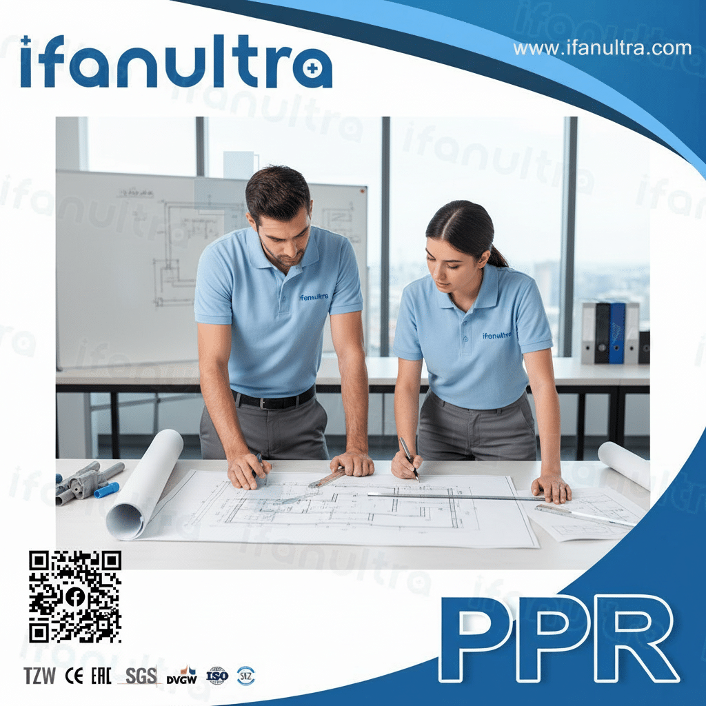
This foundational phase is where the project’s success is truly determined. It’s less about pipes and more about answering critical questions. Rushing through it is like building a house without a blueprint. We need to establish a solid base before any detailed design can begin. This phase typically involves multiple stakeholders and focuses on three core areas.
Defining the Problem and the Goal
Every project starts with a need. Maybe it’s to increase production capacity, replace aging, unsafe piping, or comply with new environmental regulations. The planning team must work with the client to crystallize this need into a specific, measurable goal. For example, instead of “we need more water,” the goal becomes “we need a new piping system to deliver 500 gallons per minute of process water to Unit B at 80 PSI.” This clarity is essential.
Conducting the Feasibility Assessment
Is the goal technically possible with the available space, technology, and budget? This assessment looks at multiple angles. A technical review examines site constraints, soil conditions, and integration with existing infrastructure. An economic analysis creates rough cost estimates and evaluates the return on investment. Finally, a preliminary risk assessment identifies potential show-stoppers early, such as permitting issues or material supply chain problems.
Creating the Project Charter and Scope Statement
The output of this phase is a formal document, often called a Project Charter or Scope Statement. This is the project’s constitution. It authorizes the project to proceed and provides the boundaries for all future work. A well-defined scope prevents “scope creep,” where small, unplanned additions slowly blow up the budget and timeline.
| Planning Document | Primary Purpose | Key Questions It Answers |
|---|---|---|
| Feasibility Study Report | To determine if the project should proceed. | Is it technically possible? Is it financially viable? What are the major risks? |
| Project Charter | To formally authorize the project. | What is the business need? Who is the project manager? What is the high-level budget and timeline? |
| Scope Statement | To define what is included and excluded. | What specific systems will be built? What are the deliverables? What is out of scope? |
How do you create a detailed piping design and layout?
Once the plan is approved, the real engineering begins. This is where lines on a scope document start to become precise drawings. I’ve spent countless hours in this phase, where every decision impacts safety, cost, and operability.
Creating a detailed piping design involves developing precise engineering drawings like Piping & Instrumentation Diagrams (P&IDs) and Isometric Drawings, performing stress analysis, and selecting all materials, valves, and supports. The layout is optimized for safety, maintenance, constructability, and efficient process flow.
The detailed design phase is the engineering heart of the project. It translates process requirements into a buildable, safe, and efficient physical system. This stage requires close collaboration between process engineers, piping designers, structural engineers, and instrumentation teams. The work is highly iterative, with constant checks and reviews. The main deliverables from this phase provide the exact instructions for fabrication and installation.
Developing the P&IDs and Plot Plans
The Piping & Instrumentation Diagram (P&ID) is the master schematic. It shows every pipe, valve, instrument, and vessel, along with how they connect and control logic. Meanwhile, the Plot Plan is the “overhead view” that places all this equipment on the actual site, defining the plant’s footprint. These two documents are the primary guides for all subsequent detailed design.
Generating Isometric Drawings and Bill of Materials
For fabrication and construction, we need more detail than a P&ID can provide. This is where isometric drawings come in. Each isometric drawing shows a single pipe run in 3D, with exact dimensions, angles, weld locations, and component callouts. From these drawings, a comprehensive Bill of Materials (BOM) is generated, listing every piece of pipe, elbow, flange, valve, and bolt needed.
Performing Engineering Analysis
Design isn’t just drawing; it’s proving the design will work. Critical analyses include pipe stress analysis (using software like CAESAR II) to ensure pipes won’t fail under pressure, temperature, or weight. Flexibility analysis checks for thermal expansion. Other reviews ensure the design meets all applicable codes (like ASME B31.3) and standards for safety and quality.
| Design Deliverable | Created By | Used By | Key Information |
|---|---|---|---|
| P&ID (Piping & Instrumentation Diagram) | Process Engineer | All disciplines | Process flow, equipment, control loops, piping specifications. |
| Plot Plan / Equipment Layout | Piping Designer | Civil/Structural, Construction | Physical location of all major equipment and structures. |
| Piping Isometric Drawing | Piping Designer/Drafter | Fabricator, Pipefitter | Exact dimensions, fittings, welds, and elevations for a specific pipe spool. |
| Pipe Stress Analysis Report | Stress Engineer | Design Reviewer, Client | Verification that piping stresses and loads are within safe limits. |
What happens during the fabrication and installation phase?
This is where the project moves from the office to the field. Seeing the first fabricated spools arrive on site is always a thrilling moment—the drawings are becoming real. But it’s also a phase of intense coordination and precision.
During fabrication and installation, pipes are cut, beveled, and welded into spools based on isometric drawings. These spools are then transported to the site, where they are lifted into place, aligned, and welded together onto pre-installed supports, following strict quality and safety procedures.
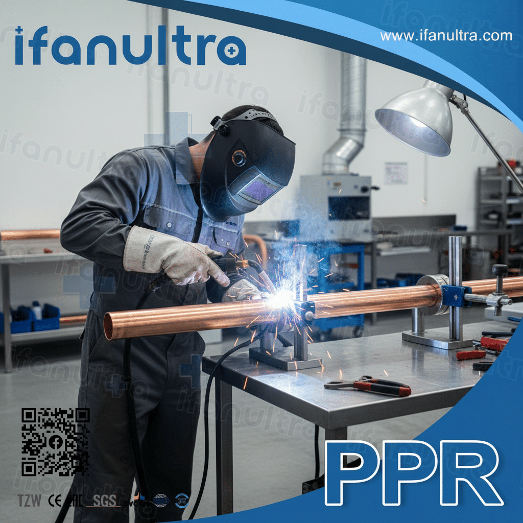
This phase is a massive logistical and technical undertaking. It splits into two parallel but connected streams: off-site fabrication and on-site installation. Effective communication between the fabrication shop and the construction site is critical to avoid delays. Quality control is paramount at every step, as fixing a faulty weld in an installed pipe is exponentially more difficult and expensive than catching it in the shop.
Off-Site Fabrication: Building the Puzzle Pieces
Fabrication often happens in a controlled workshop environment. Using the isometric drawings, steel pipes are cut to length, beveled for welding, and sometimes bent. Components like elbows, tees, and flanges are welded on to create complete “spools.” These spools are then cleaned (e.g., sandblasted), painted or coated, and inspected. Non-Destructive Testing (NDT) like X-ray or ultrasonic testing is performed on critical welds to ensure they are sound before the spool leaves the shop.
On-Site Installation: Assembling the Puzzle
Meanwhile, on the construction site, foundations are poured, and pipe supports (hangers, guides, anchors) are installed according to the design. When fabricated spools arrive, they are carefully lifted and maneuvered into position—a task that requires skilled crane operators and riggers. Pipefitters then align the spools, check for fit-up, and complete the final site welds to connect everything. This requires precise measurement and adjustment.
Coordination, Safety, and Quality Surveillance
This phase is a hub of activity with multiple trades working simultaneously—pipefitters, welders, electricians, insulators. Daily coordination meetings are essential. Safety is the top priority, with protocols for hot work permits, confined space entry, and working at heights. Quality surveillance involves visual weld inspection, reviewing NDT reports, and ensuring installation matches the approved drawings.
| Fabrication/Installation Activity | Location | Key Personnel | Quality Check |
|---|---|---|---|
| Spool Fabrication | Fabrication Shop | Welder, Fitter | Dimensional Check, Weld NDT (X-ray) |
| Surface Preparation & Coating | Blasting/Painting Shop | Coating Inspector | Dry Film Thickness measurement |
| Support Installation | Construction Site | Ironworker, Civil crew | Anchor bolt location & elevation check |
| Spool Erection & Fit-Up | Construction Site | Pipefitter, Rigger | Laser alignment, Gap measurement before welding |
| Final Site Welding | Construction Site | Welder | Visual inspection, Weld log documentation |
How is a piping system tested and commissioned for use?
After all the pipes are installed, the job isn’t done. This final phase is about proving the system works as intended and is safe for operation. I’ve seen the tension in a control room during the first pressure test—it’s the ultimate exam for the entire project team.
A piping system is tested and commissioned through a series of rigorous checks: Hydrostatic or Pneumatic Pressure Testing to verify strength and leak-tightness, followed by flushing, cleaning, and functional tests of all instruments and valves. Finally, the system is introduced to the process fluid and monitored during initial startup.
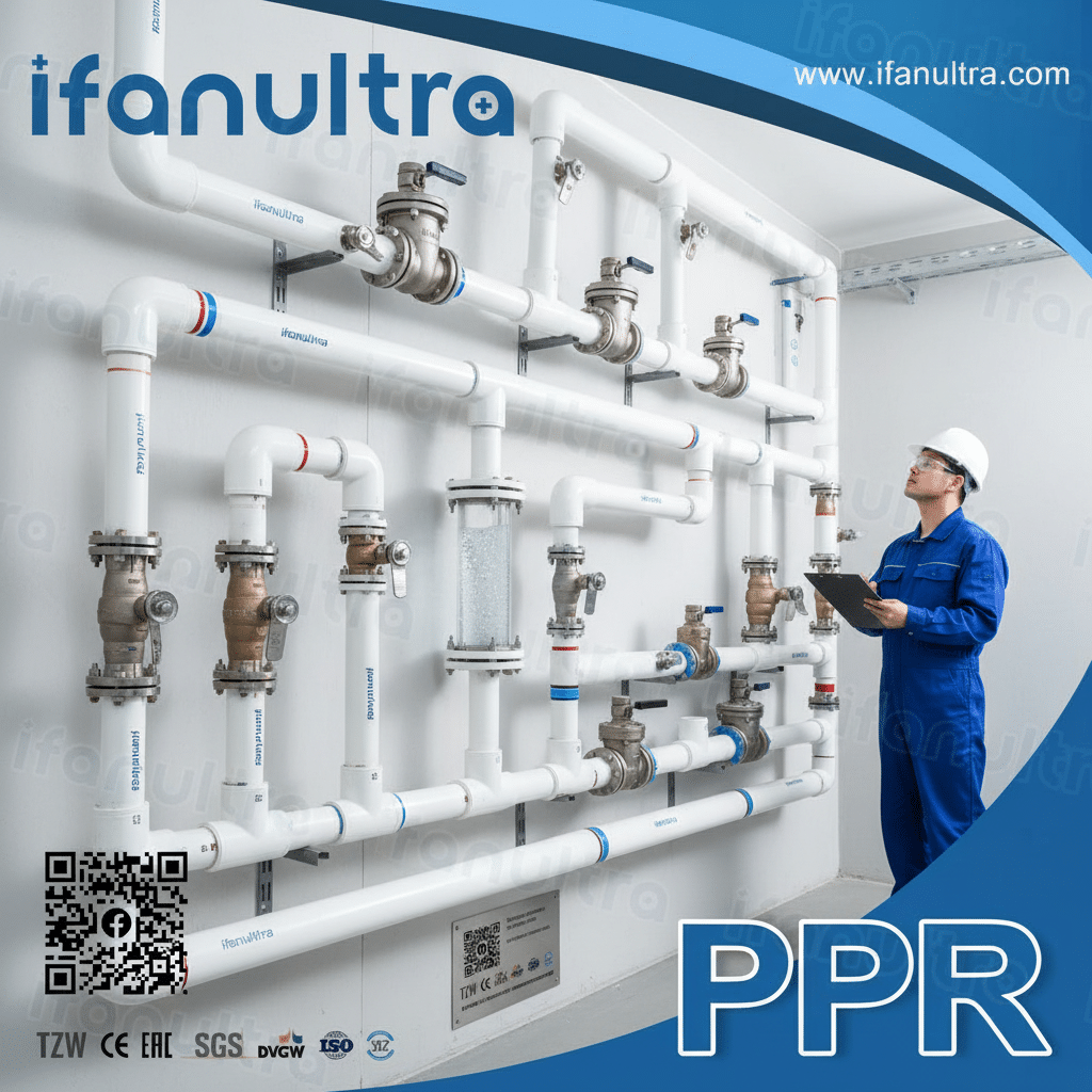
Testing and commissioning is the project’s grand finale. It’s a systematic process of verification, cleaning, and gradual handover from the construction team to the operations team. The goal is to ensure integrity, remove construction debris, and confirm that every component functions correctly under simulated and real operating conditions. Skipping or rushing these steps can lead to catastrophic failures or prolonged startup problems.
Pressure Testing: Proving Structural Integrity
The most critical test is the pressure test. For most systems, a hydrostatic test is performed—filling the pipes with water and pressurizing them to 1.5 times the design pressure for a specified time. Inspectors look for any drops in pressure or visible leaks. For systems that cannot tolerate water, a pneumatic test (using air or nitrogen) may be done, but with extra safety precautions due to the stored energy in compressed gas. This test validates the design, materials, and workmanship of all welds and joints.
Cleaning and Flushing: Ensuring Purity
After pressure testing, the test water is drained, and the system must be thoroughly cleaned. Construction leaves behind dirt, weld slag, and metal shavings that could damage pumps, clog instruments, or contaminate the product. Techniques include mechanical flushing with high-velocity water, chemical cleaning, or steam blowing. The cleanliness is often verified by inspecting filter screens or analyzing fluid samples.
Pre-Commissioning and Functional Checks
Before introducing the process fluid, every movable part is checked. This includes calibrating instruments (pressure gauges, temperature sensors), stroking control valves to ensure they open and close on command, and verifying the operation of safety relief valves. Control systems are loop-checked to confirm that field instruments correctly communicate with the control room.
Commissioning and Startup
This is the final transition. The system is slowly filled with the actual process fluid (oil, gas, chemicals). Operations personnel take over control, following a detailed startup procedure. The system is gradually brought up to pressure and temperature while being closely monitored for any anomalies. Once stable operation is achieved, the project is formally handed over to the client, marking the end of the construction timeline and the beginning of the asset’s operational life.
Conclusion
From initial concept to final handover, a piping project’s timeline is a disciplined journey. Each milestone, from planning to commissioning, is a critical step in building a system that is safe, efficient, and reliable for years to come.


 English
 Español
 Français
 Português do Brasil