
I once visited a lab where a minor leak from an incompatible pipe fitting damaged a critical experiment. This incident taught me that lab piping is not just plumbing; it’s a fundamental part of experimental integrity and personnel safety.
To design a chemical-resistant lab piping system, you must systematically map all chemical exposures, select materials with verified compatibility and safety certifications, design for zero cross-contamination and easy cleaning, and implement rigorous, permanent labeling. This proactive, holistic approach prevents failure, protects research, and ensures long-term safety.
A lab’s piping is its circulatory system. A single weak point can compromise everything. Let’s break down the steps to build a robust and reliable system.
How Do You Map Chemical Compatibility for All Anticipated Lab Reagents?
Guessing compatibility is a recipe for disaster. We’ve seen projects fail because they only planned for “standard” chemicals.
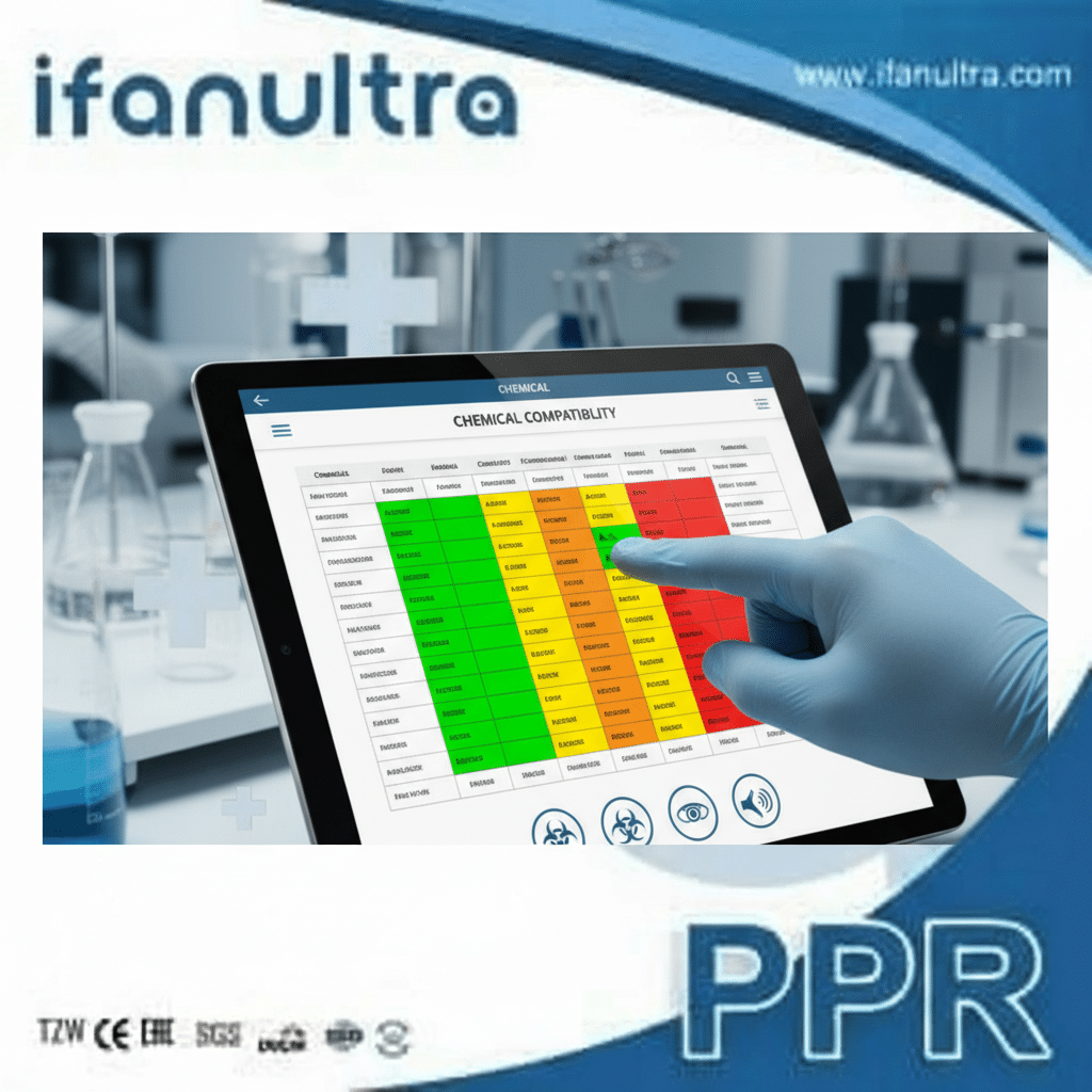
You map chemical compatibility by creating a comprehensive matrix that lists every chemical used, its concentration, temperature, and state (liquid, vapor, waste), then cross-references this data against the chemical resistance ratings of candidate piping materials like PVDF, PP, or PTFE. This process must also account for future research needs and potential accidental mixing in waste streams.
Step 1: Create a Master Chemical Inventory
The first step is gathering complete data. You cannot protect against unknown threats. Work with lab managers, principal investigators, and safety officers to list every reagent. Do not forget:
- Primary Reagents: Acids (e.g., HCl, HNO₃), bases (e.g., NaOH, KOH), solvents (e.g., acetone, dichloromethane).
- Secondary Exposures: Cleaning agents, sanitizers, and disinfectants used on surfaces.
- Process Byproducts & Waste: Chemical mixtures in drain lines can react, creating more aggressive compounds. Waste streams are often more corrosive than the original chemicals.
- Concentration & Temperature: A dilute acid at room temperature is very different from a concentrated, hot acid. Note the maximum expected values for both.
Step 2: Understand Material Failure Modes
Different plastics fail in different ways. Compatibility is not a simple “yes/no.” You must understand the risks:
- Absorption & Swelling: The plastic soaks up the chemical, gets soft, and loses structural strength. This can lead to pipe sagging or joint failure.
- Chemical Attack & Cracking: The chemical reacts with the polymer chains, causing embrittlement and cracks, often seen as “crazing” on the surface.
- Extraction: Chemicals can leach plasticizers or other components out of the pipe material, contaminating your valuable research samples.
Step 3: Use and Interpret Compatibility Charts
Manufacturers provide chemical resistance charts. These are essential starting points, but use them wisely.
- Look for Ratings: Charts often use codes like “A” (Excellent), “B” (Good), “C” (Fair), “N” (Not Recommended).
- Trust Verified Data: Prefer charts from raw material producers (like Solvay for PVDF) over generic distributor charts.
- Test for Critical Applications: For high-risk or novel chemical combinations, insist on actual immersion testing. A small test coupon of the material can be immersed in the chemical and checked for weight change and physical degradation over time.
The table below gives a high-level overview of common lab-grade plastics:
| Piping Material | Best Resistance Against | Key Limitations | Typical Lab Use |
|---|---|---|---|
| PVDF (Polyvinylidene Fluoride) | Strong acids, halogens, oxidizers, high-purity applications. | Poor against strong bases (e.g., hot KOH) and some polar solvents. | Ultra-pure water, aggressive acids, halogenated waste lines. |
| PP (Polypropylene) | Broad range of acids, bases, and alcohols at room temperature. | Poor against chlorinated and aromatic hydrocarbons (e.g., benzene, toluene). | General chemical drain lines, acid/base waste. |
| PTFE (Polytetrafluoroethylene) | Virtually universal chemical resistance. | Very expensive, difficult to fabricate, cannot be thermally welded. | Liner for steel pipes, specialized probe lines, extreme applications. |
| CPVC (Chlorinated Polyvinyl Chloride) | Good acid resistance, cost-effective. | Poor against many solvents and bases. Not for high purity. | Secondary containment, certain dedicated acid lines. |
Final Tip: Always design for the worst-case scenario, not the average. Map for the highest concentration, hottest temperature, and most complex waste mixture you can envision.
Why Are Material Certifications Like USP Class VI Critical for Lab Safety?
Using “industrial” pipe in a lab can introduce invisible risks that compromise sensitive research.
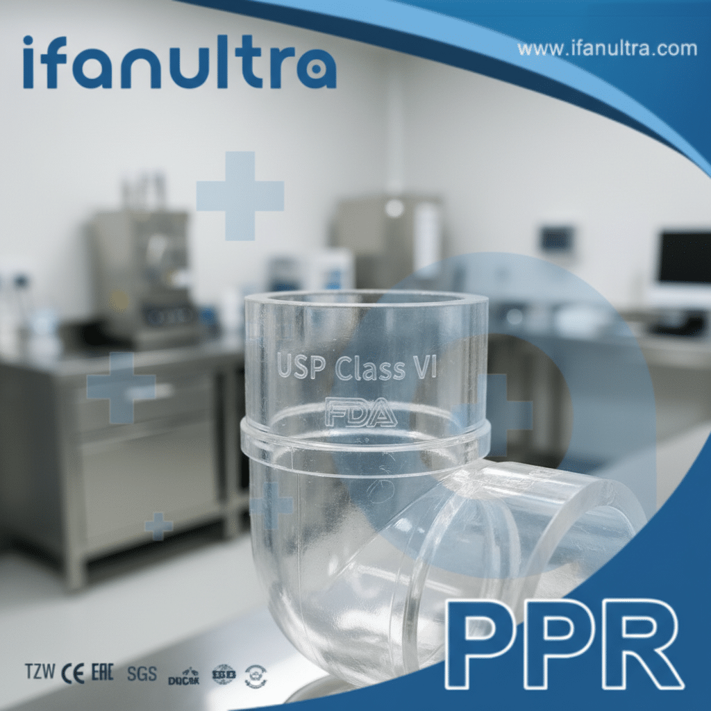
Certifications like USP Class VI are critical because they verify that the plastic material will not leach contaminants (like plasticizers or catalysts) into the fluid stream. This prevents sample contamination, ensures the validity of biological or pharmaceutical research, and guarantees the material is non-toxic and non-irritating for applications involving sensitive fluids.
Beyond Chemical Resistance: The Purity Imperative
Chemical resistance keeps the pipe from falling apart. Material certifications keep your experiments from failing. In labs, especially in life sciences, pharmaceuticals, and microelectronics, the purity of water and process fluids is paramount. Even trace levels of leachates can:
- Inhibit or kill cell cultures.
- Alter chemical reaction kinetics.
- Create false results in analytical instruments like HPLC or mass spectrometers.
- Leave residues on semiconductor wafers.
Decoding Key Certifications for Lab Piping
Understanding these certifications helps you specify the right material.
USP Class VI: This is the most stringent plastics test in the United States Pharmacopoeia. It involves implanting the material in animals to test for systemic toxicity, intracutaneous reactivity, and muscle implantation response. Passing it proves the material is highly inert and suitable for medical devices and pharmaceutical fluid handling.
- What it means for your lab: It’s the gold standard for systems carrying water for injection (WFI), cell culture media, buffers, or any fluid that contacts living organisms or final pharmaceutical products.
FDA 21 CFR 177: This U.S. Food and Drug Administration regulation lists substances permitted for use in articles intended for food contact. Compliance indicates the material is safe and will not adulterate food.
- What it means for your lab: A strong baseline indicator of material purity and non-toxicity, relevant for any lab where contamination is a concern.
Other Relevant Standards:
- EP 3.1.7 (Polyolefins): The European Pharmacopoeia equivalent, setting standards for plastics used in pharmaceutical containers and piping.
- ISO 10993: A series of standards for evaluating the biocompatibility of medical devices.
- ASTM Standards: Various standards (e.g., for extractables) that quantify what and how much leaches from a material.
How to Apply This Knowledge
- Specify by Certification: In your project specifications, state: “Piping material must be manufactured from [PVDF/PP] resin that is certified compliant with USP Class VI and FDA 21 CFR 177.”
- Request Documentation: Always ask your supplier for the official certification documents from the resin manufacturer, not just a distributor’s claim. Reputable suppliers like IFAN can provide these traceability documents.
- Match Certification to Application: Not every drain line needs USP Class VI. But for any process or ultrapure water line, it is essential. The table below provides guidance:
| Application Area | Critical Certifications to Specify | Reason |
|---|---|---|
| Pharmaceutical Manufacturing | USP Class VI, EP 3.1.7, FDA CFR | Regulatory requirement for product safety. |
| Biotech / Cell Culture Labs | USP Class VI, ISO 10993 | Prevents leachates from affecting cell growth and viability. |
| Microelectronics / High-Purity Water | Low extractables testing, FDA CFR | Prevents ionic or organic contamination on wafers. |
| General Chemical Waste Lines | FDA CFR (as a baseline) | Ensures basic material quality and safety. |
Certifications are your objective proof of purity. They move the selection process from opinion to verified fact.
How Does System Design Prevent Cross-Contamination and Ensure Cleanability?
A pipe that carries one chemical safely can become a liability if it traps residues that contaminate the next process.
System design prevents cross-contamination by using dedicated, single-use lines for critical or incompatible fluids, installing air gaps and proper drains to prevent backflow, and avoiding dead legs where fluid can stagnate. Cleanability is ensured by specifying smooth inner surfaces, using self-draining slopes, and incorporating accessible clean-in-place (CIP) ports.
Design Principle 1: Eliminate Dead Legs
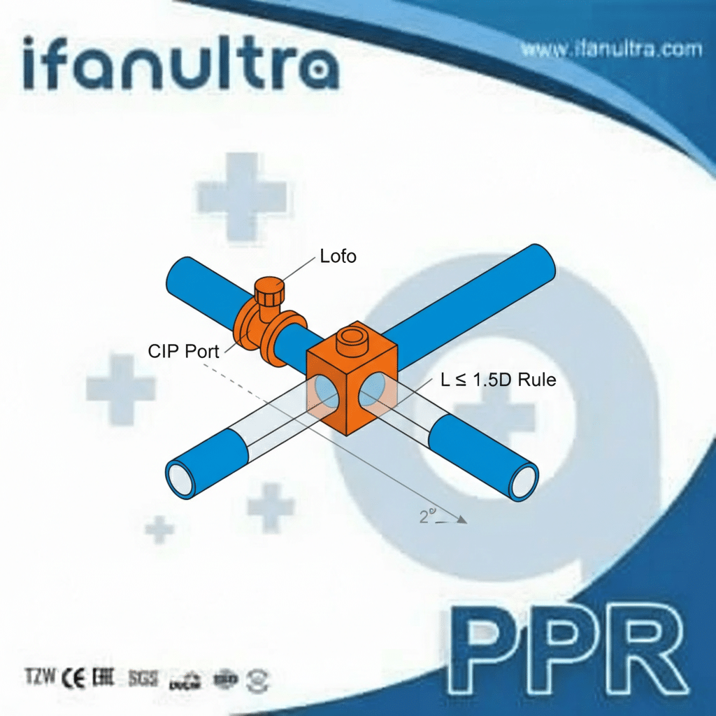
A dead leg is a section of pipe that sees little or no flow. Stagnant fluid in a dead leg is a breeding ground for microbes (in water systems) or a source of contamination when the main flow is switched.
- The Rule: The length of a branch from the main line (L) should be no more than 1.5 times its diameter (D): L ≤ 1.5D. For critical systems (like WFI), the standard is L ≤ 1.0D.
- Solution: Use diaphragm valves or zero-dead-leg valve designs at take-off points. Plan your layout so that every outlet is frequently used or can be fully flushed.
Design Principle 2: Guarantee Complete Drainage
A system that holds liquid can’t be fully cleaned or emptied for maintenance.
- Slope All Pipes: Design pipes with a continuous slope (e.g., 1-2%) toward drain points. This allows the system to be completely emptied by gravity (gravity drain-out).
- Place Drains at Low Points: Install drain valves at all system low points to remove rinse water, chemicals, or CIP solutions.
Design Principle 3: Plan for Cleaning (CIP/SIP)
Modern labs require clean-in-place (CIP) and sometimes sterilize-in-place (SIP) capabilities.
- Smooth Bore: Specify pipes and fittings with an ultra-smooth internal surface (low Ra value). This prevents bacteria and residues from adhering and makes cleaning more effective.
- CIP Supply & Return: Design a dedicated loop or connection points to introduce cleaning agents (like hot water, acids, or bases) and ensure they contact all internal surfaces before being drained.
- Access Points: Install inspection ports or “hammer unions” at key locations to allow for visual inspection or insertion of cleaning tools if needed.
Design Features to Prevent Cross-Contamination
- Air Gaps: The physical, open space between a drain pipe and the sewer line is a critical barrier. It prevents sewer gases or backups from entering the lab drainage system.
- Dedicated Lines: For ultra-pure water, solvent recovery, or specific process streams, run completely separate, labeled piping. Do not mix them in common headers.
- Proper Material Transitions: When connecting different materials, use compatible, sealed fittings to prevent crevice corrosion or galvanic cells that can become contamination sources.
The table below contrasts poor and good design practices:
| Design Challenge | Poor Practice | Good Practice |
|---|---|---|
| Sampling Point | A long, capped pipe nipple. | A zero-dead-leg sampling valve or a short, diaphragm-sealed valve. |
| System Drainage | Pipes run level with no low-point drains. | All pipes sloped to drain valves; use saddle drains on main headers. |
| Line Sharing | One waste line for all solvents and acids. | Separate dedicated lines for halogenated, non-halogenated, and acid waste. |
| Cleaning | System must be manually disassembled to clean. | Designed with CIP capabilities, including spray balls for tanks and looped circuits. |
Good design thinks about the entire lifecycle—installation, daily use, maintenance, and modification. It builds in safety and cleanliness from the start.
What Are the Best Practices for Labeling and Documenting Lab Piping Networks?
Unlabeled pipes are a safety hazard and a maintenance nightmare. Good documentation turns a maze of pipes into a manageable asset.
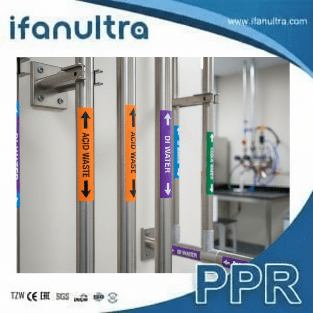
Best practices include using permanent, color-coded labels that follow industry standards (e.g., ASME A13.1), placing them at all valves, junctions, and every 20-25 feet of straight run, and maintaining a live “as-built” diagram that documents the material, content, flow direction, and all changes made to the system over time.
The Labeling Standard: More Than Just Text
Effective labels communicate instantly, even in an emergency.
- Color Coding (ASME A13.1 Standard):
- Yellow with Black Text: Flammable fluids (e.g., solvents, alcohols).
- Green with White Text: Potable, cooling, or process water.
- Blue with White Text: Compressed gases (air, nitrogen).
- Red with White Text: Fire-quenching fluids (sprinkler lines).
- Orange with Black Text: Toxic or corrosive fluids (acids, bases, chemical waste).
- Brown with White Text: Combustible fluids (oils).
- Purple with White Text: Advanced fluids (like deionized water).
- Label Content: Each label should clearly state:
- Content: e.g., “18 MΩ DI WATER,” “HCL 10% WASTE,” “COMPRESSED AIR.”
- Flow Direction: An arrow indicating which way the fluid flows.
- Hazard Warnings: Optional but helpful symbols (corrosion, health hazard).
- Durability & Placement: Use laminated, chemical-resistant labels or embossed plastic tags. Place them on both sides of walls/barriers, before and after valves, and at any point where the pipe changes direction.
The Documentation System: The “As-Built” Bible
The installation drawings are just the beginning. The system must be documented as it is actually built and every time it is modified.
Essential Documents to Maintain:
- Updated P&IDs (Piping and Instrumentation Diagrams): The master schematic showing every pipe, valve, instrument, and vessel.
- Material Traceability Records: Certificates for every batch of pipe, fitting, and valve used.
- Welding/Joinery Logs: For thermally welded systems (like PP or PVDF), records of the welder, machine settings, and weld coupons tested.
- Pressure Test Reports: Documentation proving the system was tested and held pressure.
- Chemical Compatibility Matrix: The final, approved matrix used for material selection.
Practical Tip: Go Digital. Use a simple cloud-based system or a dedicated facility management software to store these documents. When a modification is made, the technician must update the digital P&ID on a tablet before closing the wall. This keeps the “as-built” truly current.
A Simple Maintenance Table
Create a simple log for ongoing system integrity. Here is an example:
| Pipe Section ID | Content | Material | Installation Date | Last Inspection/Clean Date | Notes/Modifications |
|---|---|---|---|---|---|
| WW-101 | Acid Waste (Mixed) | PVDF, SDR 11 | Oct 2023 | Apr 2024 | Flushed quarterly. No issues. |
| DI-202 | Deionized Water | PVDF, USP Class VI | Oct 2023 | Mar 2024 | Monthly microbial testing passed. |
| CW-301 | Chilled Water | PP-R | Oct 2023 | — | No maintenance required. |
Labeling and documentation are not administrative chores. They are active safety systems that prevent accidents, speed up repairs, and protect your multi-million dollar lab investment.
Conclusion
Designing a safe lab piping system requires meticulous planning in compatibility, certification, cleanable design, and clear documentation. For reliable, certified PVDF and PP piping components that meet these rigorous standards, partner with IFAN for your laboratory infrastructure.


 English
 Español
 Français
 Português do Brasil