
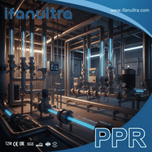
I once reviewed a system where pumps were constantly overworking. The culprit wasn’t the pump—it was the poor fittings that created hidden resistance, wasting energy every single day.
Fittings impact overall fluid flow efficiency by introducing resistance, which causes pressure drops and turbulence. This forces pumps to work harder, using more energy to move the same volume of fluid. Optimized fittings with smooth interiors and streamlined geometry minimize this resistance, directly reducing energy consumption and operational costs in any fluid system.
While pipes get most of the attention, fittings are the critical control points for system efficiency. Let’s examine how their design makes a major difference.
How Do Internal Diameter and Smoothness Reduce Turbulence and Pressure Drop?
We see systems with undersized fittings all the time. It’s like trying to breathe through a narrow straw; the system struggles.
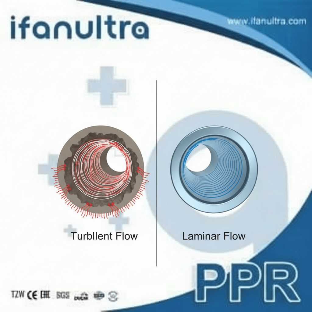
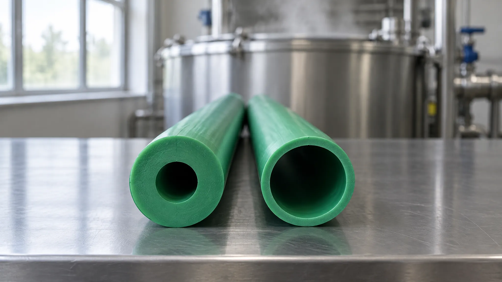
A fitting’s internal diameter (ID) and wall smoothness reduce turbulence and pressure drop by providing a consistent, unobstructed path for fluid. A matching or generous ID prevents flow constriction, while a smooth surface minimizes friction between the fluid and the fitting’s wall, allowing laminar (smooth) flow to be maintained for longer distances with less pump energy required.
The Direct Link Between Friction and Energy Loss
When fluid moves through a pipe or fitting, it interacts with the inner wall. This interaction creates friction. Friction converts the fluid’s kinetic energy (movement energy) into heat, which dissipates uselessly. This loss of useful energy is the “pressure drop.”
Here’s how ID and smoothness combat this:
- Internal Diameter (ID): If a fitting’s ID is smaller than the pipe it connects to, it creates a sudden constriction. The fluid must accelerate sharply to squeeze through, causing violent turbulence and a significant pressure drop. Even after exiting the fitting, the flow remains chaotic for a long distance, wasting more energy. A proper fitting maintains a consistent ID.
- Surface Smoothness: Imagine dragging a box over a rough road versus a smooth ice rink. The rough surface creates more drag. Similarly, a rough or pitted inner surface in a fitting creates countless tiny eddies and disturbances, increasing friction. A hydraulically smooth surface offers minimal resistance, allowing the fluid’s core to slide past with less energy loss.
Real-World Consequences of Poor ID and Finish
The impact isn’t just theoretical. In one case, a client used low-quality elbows with a significantly reduced ID and rough casting seams. The measured pressure drop across a single elbow was 30% higher than across a premium fitting. In a system with dozens of elbows, this required a larger, more expensive pump and led to 15% higher annual energy costs just to overcome this unnecessary friction.
Key Factors to Check:
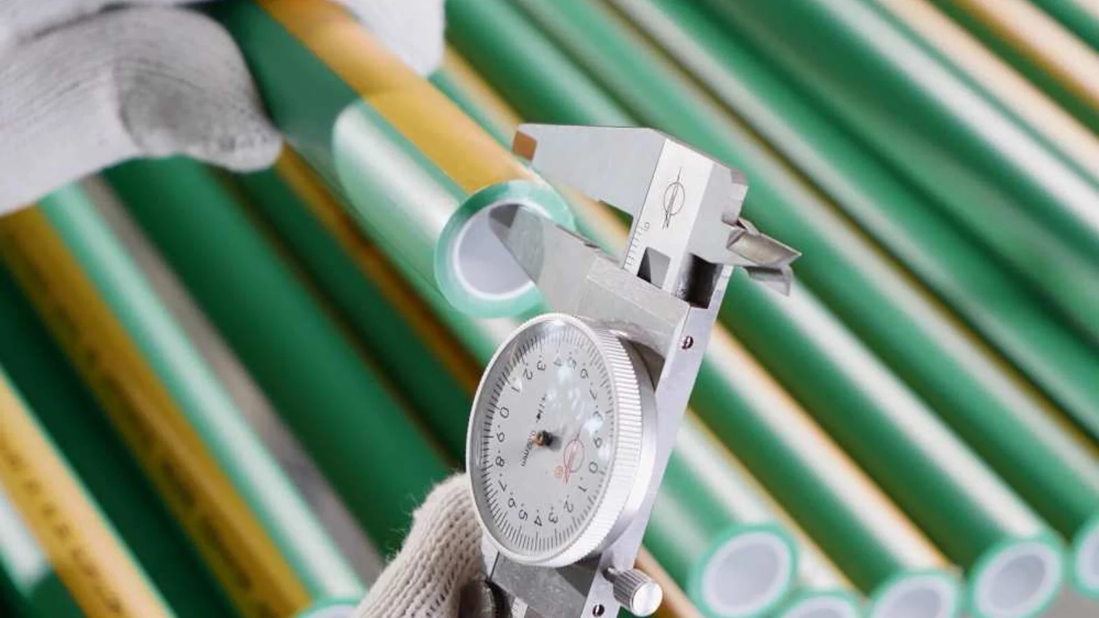
- Dimensional Consistency: Ensure the fitting’s specified ID matches your pipe’s ID. Don’t just trust the nominal size (e.g., “1 inch”); ask for the actual measured bore diameter.
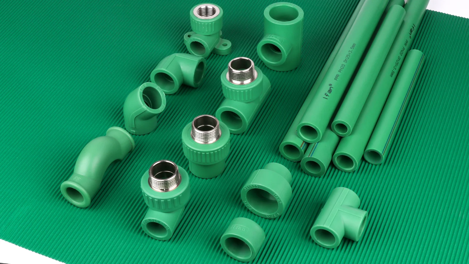
- Material and Manufacturing: Injection-molded thermoplastics (like PP-R) often have superior inherent smoothness compared to some cast metal fittings. The molding process creates a consistent finish.
Comparing Friction Loss in Different Fitting Types
The table below illustrates how fitting choice directly influences system resistance. These are relative values for comparison.
| Fitting Type (for same nominal size) | Relative Pressure Drop | Primary Cause of Loss |
|---|---|---|
| Long-Radius Sweep Elbow | Low | Gentle directional change minimizes flow separation. |
| Standard 90-Degree Elbow | Medium | Sharper turn creates more turbulence. |
| Tee (Straight Run) | Low | Minimal disturbance to straight flow. |
| Tee (Branch Flow) | Very High | Fluid must make a 90° turn against inertia. |
| Poor-Quality Reducer | High | Abrupt diameter change causes severe turbulence. |
| Streamlined, Smooth-Bore Fitting | Lowest | Consistent ID and hydraulic smoothness. |
Choosing fittings for a smooth, consistent bore is the first and most critical step in designing an efficient system.
Why Does Optimized Fitting Geometry Minimize Energy Loss in Pumped Systems?
Pumps are the heart of a system, and every fitting influences how hard that heart has to work. Optimized geometry is like keeping the arteries clear.
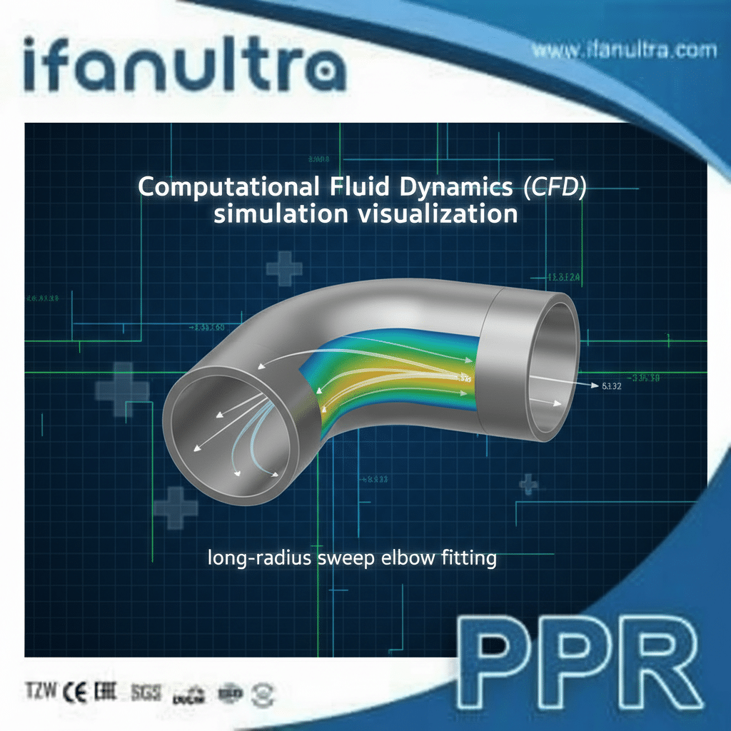
Optimized fitting geometry minimizes energy loss by guiding fluid through directional changes gradually. This prevents the flow from separating from the inner wall and creating energy-wasting vortices and turbulence. Fittings like long-radius elbows, sweeping bends, and Y-junctions are designed to maintain laminar flow, which requires significantly less pumping power than turbulent flow.
The Physics of Flow Direction Changes
When fluid in motion hits a sharp corner, it can’t follow the wall. It separates, creating a low-pressure, turbulent vortex zone in the corner. This vortex acts like a brake, sucking energy out of the main flow. The pump must then supply extra energy to overcome this brake.
Optimized geometry addresses this by making the turn more gradual:
- Long-Radius Elbows vs. Short-Radius Elbows: A long-radius elbow (with a centerline radius 1.5 times the pipe diameter or more) gives the fluid a gentle path to follow. The flow stays attached to the wall, separation is minimized, and the pressure drop can be up to 50% less than in a standard short-radius elbow.
- Sweeping Bends: For the lowest possible loss, a custom-swept bend is ideal. It offers the most gradual turn possible.
- Y-Junctions vs. Standard Tees: When flow needs to split, a standard tee forces fluid to slam into a dead end and make a sharp 90-degree turn. A Y-junction, angled typically at 45 or 30 degrees, allows the branching flow to diverge smoothly, dramatically reducing resistance.
The Cumulative Effect on Pump Load
A single fitting’s loss might seem small. But in a commercial building or industrial process, a system may contain hundreds of directional changes. The cumulative pressure drop from poor geometry can be enormous.
Example Calculation:
Assume a system needs 50 psi of pressure at the endpoint.
- With optimized fittings, the total pressure drop from friction in the entire pipe run might be 20 psi. The pump therefore needs to generate 70 psi (50 + 20).
- With poor-geometry fittings, the friction loss might increase to 35 psi. Now the pump must generate 85 psi.
The pump in the second scenario works 21% harder ((85-70)/70) just to overcome bad fittings. This translates directly into higher electricity consumption, more wear on the pump, and greater operating costs.
Geometry Selection Guide for Common Fittings
This table helps choose the right shape for the job.
| Application Goal | Recommended Fitting Geometry | Reason & Benefit |
|---|---|---|
| Minimize Energy Use | Long-radius elbows, Sweeping bends | Lowest pressure drop per direction change. |
| Split Flow with Minimal Loss | Y-junction or laterals | Smooth flow diversion reduces turbulence. |
| Limited Space Constraint | Short-radius elbow | Accepts higher energy loss for compact layout. |
| Mixing Two Fluid Streams | Specific mixing tees or nozzles | Designed to combine flows efficiently without hammer. |
Always prioritize gentle geometry in the main flow lines, especially on the pump’s discharge side where pressure and velocity are highest.
How Can Poor Fitting Selection Increase Operational Costs Over Time?
The cheapest fitting on the shelf is often the most expensive one installed. We see clients pay for this mistake for years through their utility bills.
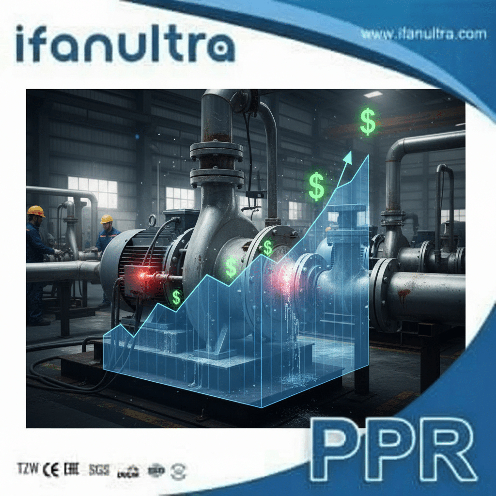
Poor fitting selection increases operational costs through three main channels: 1) Higher energy consumption due to increased pump work against friction, 2) More frequent maintenance and replacement of overtaxed pumps and valves, and 3) Potential process downtime or reduced output due to inadequate flow or pressure at critical points in the system.
Breaking Down the Cost of Friction
The financial impact of inefficient fittings is persistent and measurable. It’s not a one-time penalty but a continuous drain.
1. Energy Costs (The Biggest Drain): As detailed earlier, poor fittings cause higher pressure drops. This directly increases the pump’s “duty point”—the combination of head (pressure) and flow it must provide. Pumps consume more electricity to produce higher head. For a constantly running industrial pump, even a small percentage increase in required pressure leads to a large annual energy bill.
2. Maintenance and Capital Costs:
- Pump Wear: A pump working against higher system resistance runs at a higher stress level, often farther from its best efficiency point (BEP). This leads to increased wear on seals, bearings, and impellers, resulting in more frequent repairs and shorter pump life.
- Valve Wear: Turbulent, high-velocity flow from fittings can cause cavitation and erosion in downstream control valves, damaging trim and seats.
- Premature Replacement: The entire system—pumps, valves, even the fittings themselves—may need replacement sooner than expected due to the harsh operating conditions created by poor initial selection.
3. Production or Performance Loss:
In a factory, if a cooling water loop doesn’t deliver the required flow due to fitting-induced pressure drops, a machine may overheat and shut down, causing production loss. In an HVAC system, it can lead to uneven heating or cooling and occupant complaints.
A Simple Cost Comparison Over 5 Years
Consider a single mid-sized circulation pump (30 kW) running 24/7.
| Cost Factor | System with Optimized Fittings | System with Poor Fittings | Notes |
|---|---|---|---|
| Extra Pump Head Required | +0 psi (Baseline) | +15 psi | Due to high-loss fittings. |
| Estimated Energy Increase | 0% | ~12% | Pump must work harder. |
| Annual Energy Cost | $15,000 | $16,800 | At $0.10/kWh. |
| 5-Year Energy Cost | $75,000 | $84,000 | $9,000 extra wasted. |
| Estimated Pump Maintenance | Standard | High | More frequent repairs. |
| Risk of Downtime | Lower | Higher | From pump failure or low flow. |
The extra $9,000 in energy alone could have paid for a full premium piping system. This clearly shows that the true cost of a fitting is its lifetime operating cost, not just its purchase price.
What Should You Analyze When Selecting Fittings for High-Flow Systems?
Selecting fittings for high-flow systems requires more than just matching the pipe size. It requires a strategic approach to preserve energy and system integrity.
When selecting fittings for high-flow systems, analyze these four key factors: 1) Pressure Drop Data, using manufacturer charts or flow coefficients (Kv/Cv values); 2) Internal Geometry, prioritizing long-radius turns and smooth transitions; 3) Material and Erosion Resistance, especially for abrasive fluids; and 4) Velocity Profiles, ensuring fittings do not create localized high-speed jets that cause cavitation or wear.

A Step-by-Step Selection Checklist
High flow rates magnify the impact of every fitting. A small inefficiency is multiplied by a large volume of fluid, leading to massive energy penalties.
1. Pressure Drop Analysis:
This is the most critical technical step. Do not guess.
- Use Flow Coefficients: Reputable manufacturers provide Kv (metric) or Cv (imperial) values for their fittings. These numbers quantify how much flow will pass through the fitting at a given pressure drop. A higher Kv/Cv means less resistance. Always compare these values between brands.
- Consult Flow Charts: Many engineering resources provide equivalent length charts. They tell you that a particular elbow adds the same resistance as a certain length of straight pipe. Use this to calculate total system pressure drop.
2. Geometric and Design Analysis:
- Radius is King: For every elbow or bend, specify the longest radius that space allows.
- Avoid Abrupt Changes: Use concentric reducers/expanders instead of eccentric ones where possible, unless draining is an issue. Ensure bore alignment is perfect.
- Consider Installation: Can the fitting be installed in the correct flow orientation? A misaligned sweep elbow can do more harm than good.
3. Material and Durability Analysis:
High flow often means high velocity, which can lead to erosion.
- Abrasive Fluids: For slurries or fluids with particles, material hardness and wear resistance become paramount. Consider thicker walls or special alloys.
- Water Hammer: For systems with quick-closing valves, ensure the fitting material and pressure rating can handle potential surge pressures.
Critical Specification Table for High-Flow Fittings
Use this as a guideline when reviewing manufacturer catalogs or quotes.
| Parameter | What to Look For | Why It Matters |
|---|---|---|
| Flow Coefficient (Kv/Cv) | The highest value available for the fitting type. | Directly indicates lower pressure drop and higher efficiency. |
| Internal Bore | Fully characterized, smooth, matching pipe ID. No ridges or steps. | Prevents turbulence and flow separation at the connection. |
| Elbow Radius | Long-radius (R=1.5D or greater). | Minimizes energy loss at directional changes. |
| Material & Wall Thickness | Suitable for fluid; adequate thickness for pressure and erosion. | Ensures system longevity and safety under high-flow conditions. |
| Manufacturing Standard | Compliance with ISO, ASTM, or other relevant standards. | Guarantees dimensional accuracy and performance consistency. |
Finally, always model your complete system. Use hydraulic modeling software or consult with an engineer to sum the pressure drops of all components (pipes, fittings, valves) to ensure your pump selection is correct and energy-efficient. Choosing fittings in isolation is a common mistake; they must be evaluated as part of the whole system.
Conclusion
Fittings are critical control points for system efficiency, directly impacting energy use and cost. For flow-optimized solutions that reduce pressure drop, specify IFAN’s hydraulically efficient fittings designed with smooth bores and optimized geometry.


 English
 Español
 Français
 Português do Brasil